Custom Search
|
|
 
|
||
|
THE 5/54 MK 45 MOD 0 GUN MOUNT POWER DRIVE The power drives for the 5"/54 Mk 45 Mod 0 gun mount consists of the train and elevation power drives. The train power drive responds to one set of order signals to rotate the carriage, while the elevation power drive responds to another set of order signals. Activation of the power drives occurs as follows: 1. The elevation and train motors are started. The elevation motor is started first because it furnishes servo and supercharge fluid to both the elevation and train power drives. 2. The power-off brakes release when a mode of operation is selected. 3. After being assigned to a fire control system by weapons control, the mount trains and elevates in response to a remote signal. The power drives for the 5"/54 Mk 45 gun mount are physically smaller than those used on the 51E/54 Mk 42 gun mounts because the Mk 45 gun mount is lighter in weight. Other than size, the main difference involves the use of only one gear pump and one auxiliary relief
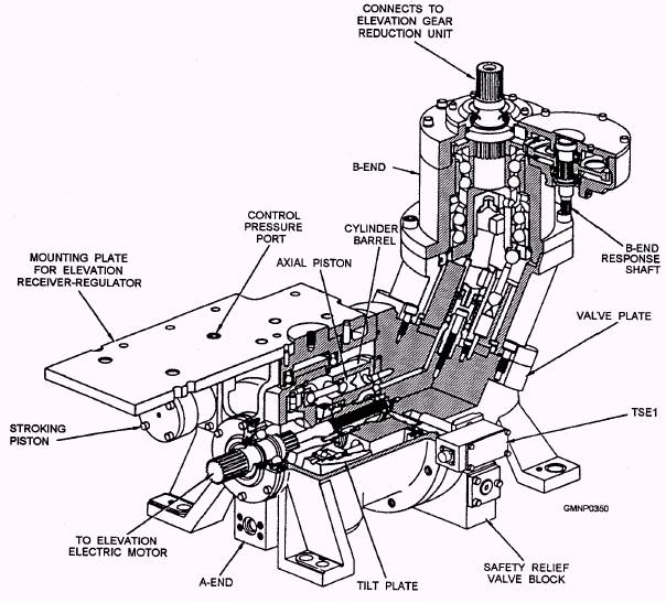
Figure 6-2.-Elevation system power drive. valve block to provide the fluid pressure for both the train and elevation power drive servo and supercharge requirements. Because the train and elevation power drives on this mount operate in a similar manner, only the elevation power drive is presented. Figure 6-2 shows the arrangement of the principal elevation power drive components. Electric Motor (5"/54) A 15-horsepower constant-speed electric motor drives the A-end of the cab unit. The train and elevation power drives are independent with their own motors. The motors are supplied with 440-volt, 60-Hz power from the EP1 panel. Hydraulic Transmission (CAB UNIT) This CAB unit (fig. 6-3) consists mainly of an A-end, a valve plate, and a B-end. Here, a brief description of how they operate is presented. A-END.- The A-end is coupled to, and driven by, the elevation electric motor. Controlled hydraulic fluid from the receiver-regulator, acting on stroking pistons in the A-end, controls the volume and direction of fluid that the A-end pumps to the B-end. The A-end output, therefore, controls the speed and direction of rotation of the B-end output shaft.
Figure 6-3.-Elevation CAB unit (cutaway view), The cylinder barrel in the A-end (fig. 6-4) contains nine pistons located axially around the drive shaft. The pistons reciprocate (move back and forth) within the cylinder bores, drawing fluid in during 180-degree rotation of the A-end and discharging fluid during the other 180-degree rotation. The volume of fluid pumped depends on the length of piston travel in the cylinder bore, which is determined by the angle of the variable tilt plate. Two stroking pistons, one on each side of the tilt plate, control the tilt plate angle. VALVE PLATE.- The stationary valve plate, located between the A-end and B-end, has two crescent-shaped ports. The valve plate keeps the fluid being drawn into the A-end separate from the fluid being discharged under pressure to the B-end. B-END.- The B-end, with its fixed-position tilt plate, operates in a reverse manner from the A-end, converting fluid flow into rotary motion. When fluid output from the A-end piston is applied to the B-end piston, the resultant thrust of the ball-end connecting rod against the inclined socket ring causes the socket ring to rotate. A universal joint connects the socket ring to the B-end output shaft so that both the output shaft and the cylinder barrel rotate with the socket ring (fig. 6-4). The cylinder barrel rotates against the two crescent-shaped ports in the valve plate. One port supplies A-end fluid to the axial pistons for a thrust stroke and the other port receives displaced fluid from the pistons on the retract stroke. During continuous rotation of the B-end, hydraulic fluid from the A-end is applied to the piston for the thrust stroke. As the cylinder bore moves past the land separating the two ports, fluid empties into the discharge port as the piston moves in the retract stroke. The discharge port for the B-end, which is replenished with supercharge fluid, connects to the intake port for the A-end. This action keeps hydraulic fluid in the CAB unit circulating within a closed loop with only supercharge fluid replenishing fluid lost through slippage. Safety Relief Valve The elevation safety relief valve (fig. 6-5, view A) is a compound relief valve, consisting of a pilot valve (UVE67), main relief valve (UVE68), and four check valves (UVE69, UVE70, UVE71, and UVE72). There are two springs in the valve block that hold UVE67 and UVE68 seated until an excessive pressure condition occurs. There are two control orifices in UVE68 that prevent pressure buildup in the CAB unit during normal operation. The safety relief valve has two functions: 1. It limits hydraulic pressure buildup in the high-pressure output line of the A-end. (It operates in conjunction with the pressure cutout switch SIE2A.) 2. It prevents pump cavitation by porting supercharge fluid to the low-pressure return line of the A-end (compensating for fluid lost through slippage and leakage). The direction of the A-end stroke determines which chamber of the valve plate ports A-end output (high
Figure 6-4.-CAB unit (mechanical schematic).
Figure 6-5.-Safety relief valve operation. pressure) fluid and which ports return (low pressure) fluid. The operation of the main relief valve, however, is independent of the direction of stroke. Figure 6-5, view A, shows the valve plate feeding A-end output to chamber A and return fluid to chamber B of the main relief valve. The valve functions in the same manner when the fluid in chambers A and B are reversed. Check valves UVE71 and UVE72 control the flow of supercharge fluid to the CAB unit valve plate. Check valves UVE69 and UVE70 allow the flow of A-end output to UVE67 while preventing its flow into the return passages. During normal operation, A-end discharge fluid pressure holds one check valve open and the other closed. With A-end discharge fluid in chamber A, UVE70 opens a passage leading to the pilot valve UVE67 in the safety relief valve block, to the pilot valve UVE16 in the auxiliary relief valve block, and to the reverse side of UVE69. When the discharge fluid pressure is in chamber B, UVE69 opens chamber B to UVE67, to UVE16, and to the reverse side of UVE70. The plunger of the main relief valve (UVE68) has four faces of identical effective areas. These areas are in chambers A, A, B, and B. It also has identical orifices (UOE9 and UOE10) that restrict the flow of fluid from chambers A to A and from B to B. When no fluid is flowing from the lower chambers to the upper chambers, the hydraulic pressure in all four chambers is equal. When discharge fluid pressure in A and A are equalized and supercharge fluid pressure in B and B are equalized, the only effective force is the initially compressed mainspring that holds the plunger seated. When either UVE67 or UVE16 opens to the tank, it also opens chambers A and B to the tank. Any fluid flow through UVE67 or UVE16 must come from the valve plate through the two orifices and UVE70 and UVE69. The fluid pressure in the upper chambers drops below that in the lower chambers because of the orifices. When this occurs, the fluid pressure overcomes the force of the mainspring and the UVE68 plunger unseats. Now, with UVE68 unseated, A-end discharge fluid in chamber A bypasses to chamber B and into the return (low pressure) passage of the valve plate. During normal operation the conditions affecting the safety relief valve are as follows: 1. The A-end is on stroke. 2. Valve UVE16 in the auxiliary relief valve block is blocking discharge fluid. 3. The power-off brake is released. Under these conditions, UVE68 is in hydraulic balance and its plunger is seated. Any variation in the load on the CAB unit varies the discharge pressure in the valve plate. This variation acts on the top of UVE67. During normal operations, however, the fluid pressures do not exceed the preload of the UVE67 spring. Accordingly, UVE67 never bypasses fluid to the tank. With no line open to the tank, the main relief valve cannot unseat. During excessive pressure operation (fig. 6-5, view B), the conditions affecting the safety relief valve are as follows: 1. The A-end is on stroke. 2. Either the gun barrel elevates or depresses into a physical obstruction or the brake sets as the result of a power failure. (The physical obstruction could be something on deck or it could be the elevation or depression buffer.) The pressure cutout switch (SIE2A) in the tank line of UVE67 shuts down the electric motor to protect the valve plate against high temperatures developed during prolonged bypassing (more that 0.9 second). The preload of the UVE67 spring determines the hydraulic pressure required at the top of UVE67 to unseat its plunger and, in turn, to bypass discharge fluid to the tank through the slot in the plunger. Thus the two valves that determine when the main relief valve unseats are UVE67 and UVE16. When the gun elevates or depresses into a physical obstruction, pressure in the discharge passage of the valve plate rises beyond the bypass limit of the safety relief valve. This abnormally high pressure offsets the preload of the UVE67 spring and shifts the UVE67 plunger downward to bring slot S and counterbore P into line-to-line orientation. Further increase in pressure on the top of UVE67 shifts the plunger farther down to permit a proportional flow of discharge fluid to the tank through counterbore P and slot S. When the resulting flow causes the pressure in the lower chambers of UVE68 to offset the force of the mainspring, the UVE68 plunger unseats. Thus the safety relief valve keeps the discharge pressure in the CAB unit within the bypass limit. Servo and Supercharge Supply System The servo and supercharge supply system consists of a servo and supercharge pump, an auxiliary relief valve block, a servo accumulator, a charging valve, and a pair of fluid filters. This system shares the main tank and the header tank with the upper accumulator system. |
 
|
|
|
||