Custom Search
|
|
 
|
||
|
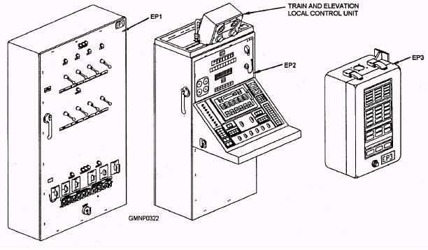
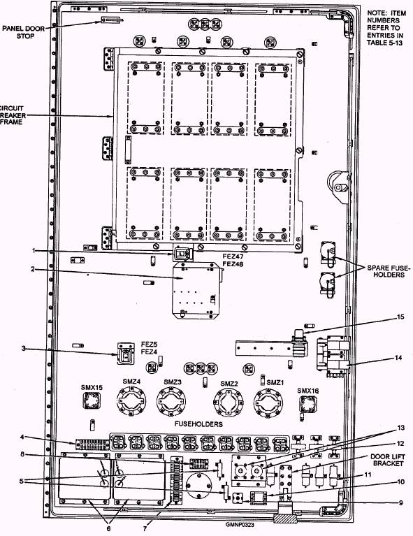
Phase-Consent and Signal-Ramp Circuits Each of the two submodules (A1 and A3) of the signal-ramp module 1J4 at the GCP (refer to fig. 5-31 and table 5-5) contains three phase-consent (square wave) circuits and three signal-ramp (sawtooth wave) circuits. These circuits generate six phase-consent signals and six signal-ramp signals. These signals, in turn, are used to control the control gate voltage to the six pairs of SCRs for the train system and the six pairs of SCRs for the elevation system. Demodulator Circuits The train demodulator circuits are located in submodules A7 and A8 of elevation amplifier module 1J3 at the GCP. These circuits rectify the 400 Hz error signals from the train synchros into a dc voltage. The dc voltage can then be used by the error amplifier circuits. The demodulator circuits use metal-oxide semiconductor field-effect transistors (MOSFET switches), operated by reference square wave signals. The MOSFET switches are used to produce the required full-wave rectification. Error Amplifier Circuits The train error amplifier circuits are located in submodule A2 of 1J3. The error amplifiers amplify and process the demodulated error signals from the synchro systems. They provide one input to the tachometer circuit. Tachometer Circuits The train tachometer circuits are located in submodule Al of 1J3. These circuits combine the output from the error amplifier and either the obstacle contouring circuit or the limit-stop circuit with a velocity output from the tachometer and a current feedback signal from the drive motors. The outputs from the tachometer circuits are order signals that, after passing through the motor current-limiter circuits, control the gating of the SCRs. Motor Current-Limiter Circuits The train motor current-limiter circuits are located in the current-limiter module in the bottom compartment of the GCP. These circuits monitor the current feedback from the electric drive motors. If the drive motor draws high levels of current longer than the short time required for normal acceleration, the current-limiter circuit reduces the order signal. This, in turn, reduces the current applied to the drive motors. TRAIN SECURING MECHANISM The train securing mechanism locks the carriage to the stationary outer ring of the roller path assembly when the gun is stowed. The train securing mechanism consists of a stowing pin shifting lever, a train stowing pin, and the train stowing pin handle. A proximity switch, mounted behind the stowing pin handle, is actuated when the stowing pin is engaged. The stowing pin handle is on the left side of the mount and extends down into the ammunition handling room. The proximity switch lights the TRAIN LOCK IN lamp at the GCP. With the stowing pin engaged, the train amplifier ready circuit is disabled, in turn, disables the train motor start circuit. MK 45 GUN MOUNT CONTROL SYSTEM LEARNING OBJECTIVE: Identify the components of the Mk 45 gun mount control system. Components of the Mk 45 gun mount control system control and distribute power to the gun-loading and gun-laying systems. The power panel EP1, located in the loader room, distributes power to the control components. The control panel EP2, also located in the loader room, controls the gun mount operations and provides a means for testing and exercising the gun-laying and the gun-loading systems. The display panel EP3, located adjacent to the lower loading station, displays round orders for ammunition handlers. The gun mount control system also includes position sensors (proximity and optical switches), relays, and solenoids that activate, control, monitor, and test operations of the gun mount. Solid-state logic and microprocessor circuits in the EP2 interlock and sequence the cycles of gun-loading system components and also control electric motor operation. The panels of the control system (fig. 5-59) are as follows: 1. Power panel (EP1) 2. Control panel (EP2) 3. Train and elevation local control unit 4. Display panel (EP3) Individual components of the gun mount control system are located throughout the gun mount. This section will cover only a general description of the Mk 45 gun mount control system. For a more detailed and in-depth description, refer to the Technical Manual for 5-Inch 54-Caliber Gun Mount Mark 45, SW323-D1-MM0-010/GM MK 45 series. POWER PANEL EP1 Power panel EP1 contains the electrical power-distribution and power-converting components of the gun mount control system. Power from the ship's 440 VAC normal or alternate supplies enters EP1 and passes through circuit breakers and contractors to the drive motors. A step-down transformer in EP1 reduces the 440 VAC motor supply to 115 volts for control, lighting, anti-icing, and test purposes. Panel EP1 contains motor contractors, overload relays, manual interlock switches, +25 VDC power supplies for solenoids, lights, switch circuits, a fan, batteries, battery chargers, an electronic component assembly, ac output driver circuit cards, resistors, capacitors, rectifiers, relays, fuses, and terminal boards. A solenoid door latch prevents the panel door from being opened when normal or alternate 440 VAC is applied to the panel. Figure 5-60 shows the back of the EP1 door, and table 5-13 is a list of the components
Figure 5-59.-Electrical control system panel.
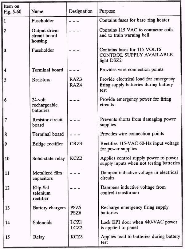
Figure 5-60.-Power panel EP1 (back of door). Table 5-13.-Power Panel EP1-Back of Door
mounted on the back of the door. Figure 5-61 shows the interior of EP1, and table 5-14 lists the components inside of the EP1. |
 
|
|
|
||