Custom Search
|
|
 
|
||
|
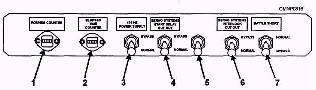
Elapsed Time Counter CO The ELAPSED TIME COUNTER CO is also located inside the top cover of the GCR The counter CO allows the gun crew to monitor the running time of the gun mount for maintenance purposes. Counter CO operates whenever 115 VAC 400 HZ servo power is on (refer to fig. 5-53 and table 5-12). MK 75 TRAIN AND ELEVATION SYSTEM LEARNING OBJECTIVE: Recall general information about the Mk 75 gun mount train system and its six major components. The train and elevation systems position the gun in response to gun-laying orders from the fire control system (FCS) or from the gun control panel (GCP). The train and elevation systems use low-inertia dc drive motors with reduction gearing as power drives. Both systems also use conventional synchros with associated power supplies and electronic control systems to regulate current to the motors. The train and elevation systems consist of two independent but similar power drives, power supplies, and control systems. Because of their similarity, only the train system will be discussed in this section. A more detailed description of the train and elevation system can be found in the Technical Manual for 76-mm 62-Calibre Gun Mount Mark 75 MODS 0 and 1, SW314-AO-MMM-A10/GM MK 750-1 series.
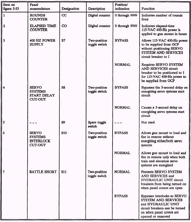
Figure 5-53.-Switch and counter board assembly. Table 5-12.-GCP: Controls and Indicators (Top Cover Open)
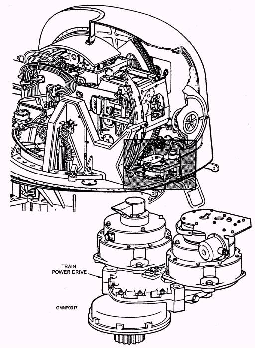
The train system consists of strain power drive (fig. 5-54) that is mounted on the rear platform of the carriage. The power drive moves the gun mount around the stationary ring of the roller path assembly in response to train positioning orders. Train movement is unlimited due to a slip ring assembly for electrical cabling and a rotating coupling for the barrel cooling piping. The train system consists of the following six components: 3. Train synchro control box assembly 4. Power supply 5. Motor control system 6. Train securing mechanism
Figure 5-54.-Train power drive. |
 
|
|
|
||