Custom Search
|
|
 
|
||
|
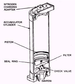
Elevation Power Drive System The elevation power drive system has two primary functions. Through its integrated hydrostatic transmission and brake assembly, it elevates and depresses the guide arms. Through its accumulator system, the elevation power drive supplies PA to operate the guide arm components. The elevation power drive is located within the launcher carriage. One electric motor drives three pumps: (1) A-end, (2) supercharge pump, and (3) guide arm PA pump. The transmission unit and the supercharge pump function like those of the train power drive system. Elevation supercharge fluid pressure is only developed to about 150 psi, however. The guide arm PA pump (gear type) delivers a volume of fluid to charge a piston type of accumulator (fig. 4-66). Guide arm PA is developed between 1,350 to 1,525 psi. A portion of this fluid is also ported to a pressure-reducing valve. This valve provides a 1,100-psi output which is used to charge a servo accumulator. Elevation servo fluid is derived from the guide arm PA. It is used to operate the elevation control assembly, position latch, and power-off brake.
Figure 4-66.-Piston type of accumulator; typical. If the elevation power drive system is running but in a standby or not operating condition, a guide arm PA accumulator solenoid will energize. The solenoid shifts a valve to block the output of the accumulator to the guide arms. (Servo fluid flow is not affected and remains available to the system.) This action prevents hydraulic slippage in the guide arm components and reduces the cycling rate of the accumulator. It also reduces heat buildup in the hydraulic fluid. RSR/Hoist Power Drive System The magazine hydraulic system consists of the A-side and B-side RSR/hoist power drive systems. They are identical units which are located within the six-missile sections and hoist ends of the RSR structures. The electric motor of each system (A and B) drives three pumps: (1) A-end, (2) case circulation pump, and (3) accumulator pump. We will only cover one side/system. The integrated hydrostatic transmission and brake assembly responds to orders from the RSR/hoist control assembly. The B-end provides a mechanical output to the RSR/hoist shifter assembly. Through this unit, the RSR is indexed or the hoist is raised and lowered. The case circulation gear pump supplies a low-volume, low-pressure circulating fluid to lubricate and cool the transmission unit. The accumulator pump (gear type) supplies fluid to the RSR/hoist accumulator system. Part of the output of the pump charges the PA/servo piston type of accumulator flask. PA/servo is developed between 1,350 and 1,525 psi and is distributed throughout the magazine equipments. These equipments include the blast door, span rail, fin opener, RSR components, hoist components, and the strikedown system. It also operates the RSR/hoist control assembly and power-off brake. The other portion of the output of the accumulator pump is applied to a pressure-reducing valve. This valve provides the hydraulic fluid that charges a supercharge accumulator flask. Supercharge fluid pressure is developed to about 400 psi and is supplied to the transmission unit. Emergency Drives Each of the four power drive systems has an emergency drive capability. A small hydraulic motor is mounted to the B-end of each transmission unit. Its output shaft is coupled to the power-off brake (fig. 4-67). When the small emergency drive motor is activated, it mechanically drives through the brake and moves the equipment. The Mk 26 GMLS does not have a manual or pneumatic means to drive through its power-off brakes. |
 
|
|
|
||