Custom Search
|
|
 
|
||
|
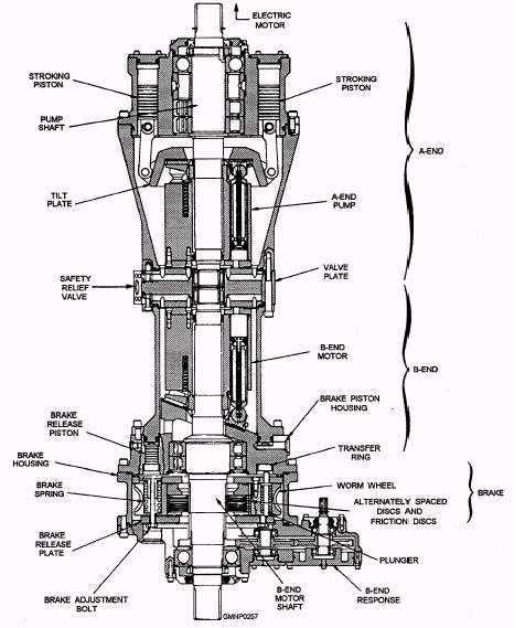
MK 13 GMLS POWER DRIVES The Mk 13 Mods 4 and 7 GMLSs have four hydraulic power drive units. Basically there are very few differences between the power drives of the various mods. Operating fluid pressures do vary and only average ranges will be noted. The launcher guide power unit (LPU) is an accumulator type of power drive located in the base ring. It supplies PA to operate guide components and the blast door. A gear pump charges three accumulator flasks to develop an average operating pressure of between 1,500- to 1,600-psi PA. The magazine RSR/hoist power drive is a Special K type of unit. One A-end drives the RSR B-end or the hoist B-end. The power drive also produces servo fluid and supercharge fluid pressures. Supercharge fluid pressures are between 100 and 150 psi. Servo fluid pressure is developed by charging an accumulator flask and is about 400 psi for all mods. This fluid is supplied to the components associated with RSR/hoist selection and drive operations. Equipments include the inner and outer RSR latches, the RSR positioner, the hoist chain shifter, and the inner and outer hoist retractable rails. The train and elevation power drives are CAB type of units located in the upper part of the inner structure. The power drives are similar and function independently. Supercharge fluid pressure is about 150 psi for both train and elevation systems. Train servo fluid pressure is developed by a small accumulator and is about 525 psi for all mods. Elevation servo fluid pressure, also developed by an accumulator, averages around 440 psi. MK 26 GMLS POWER DRIVES The Mk 26 GMLS (all mods) has four primary power drive systems. Each power drive unit has a unique emergency drive capability. Also, we will encounter some different fluid pressure values. Because the Mk 26 GMLS power drives are somewhat different, especially in functional capabilities, we will present them separately. Train Power Drive System The train power drive system has only one purpose-to rotate the launcher in train. It is located under the launcher platform and above the ICS. One electric motor drives four pumps: (1) A-end, (2) lube pump, (3) supercharge pump, and (4) servo fluid pump. The main unit is the integrated hydrostatic transmission and brake assembly (fig. 4-65). This assembly is an in-line or straight CAB unit and power-off brake mounted within one housing. Physically it is different; functionally it is the same as other GMLS CAB and power-off brake units. Study this figure and compare it with figures 4-28 and 4-35. A small lube pump circulates a lubricating oil through the train reduction gear unit. The supercharge pump delivers fluid to a supercharge accumulator. Supercharge fluid pressure is developed to about 375 psi and replenishes lost fluid in the transmission unit. The servo pump delivers fluid to a servo accumulator. Servo fluid pressure is developed between 1,100 and
Figure 4-65.-MK 26 GMLS integrated hydrostatic transmission and brake assembly; typical for all main power drives. 1,400 psi. It is used to operate the train control assembly, positioner latch, and power-off brake. |
 
|
|
|
||