Custom Search
|
|
 
|
||
|
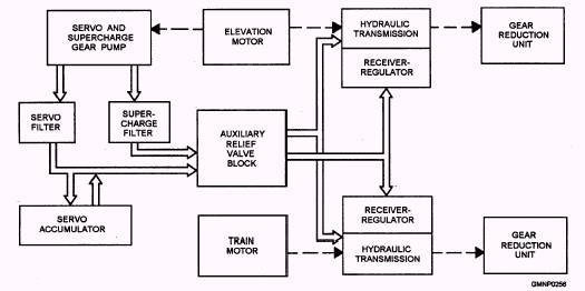
Hydraulic Control System The servo and supercharge hydraulic system (fig. 4-64) provides pressurized fluid to control and replenish the power drives. The gear pump draws fluid from the main hydraulic tank and discharges the fluid through separate outlets. The fluid goes through filters, then on to an auxiliary relief valve block, which regulates the servo pressure to about 450 psi and the supercharge pressure to about 150 psi. This valve block also controls servo fluid to a solenoid-operated valve that sets and releases the power-off brakes.
Figure 4-64.-Train/elevation hydraulic system; block diagram. The supercharge fluid goes to the valve plate of the hydraulic transmission. A series of check valves ensure that the supercharge fluid is always available to replace slippage losses in the transmission. The servo fluid, through the electrohydraulic transducer and servo valve, operates the stroking pistons of the A-end. The servo accumulator stores a small amount of fluid for periods of high demand. The accumulator also reduces pressure variations of the pump and pulsations of the relief valve. For a more detailed description of the Mk 45 hydraulic system, refer to Technical Manual for 5-Inch 54-Caliber Gun Mount Mark 45, NAVSEA SW323-D1-MMO-010 series. ACTUAL GMLS POWER DRIVES LEARNING OBJECTIVE: Explain the operation of power drive systems in the various types of GMLSs. Accumulator and CAB type of power drive systems provide a GMLS with all the hydraulic fluid forces needed to perform its functions. The primary difference between the two systems involves what their output does for the GMLS. Accumulator type of power drives produces a supply of hydraulic fluid under pressure to operate the general GMLS equipment. Electrically controlled solenoids direct this pressurized fluid to operate hydraulic cylinders, for example. CAB type of power drives produces a mechanical output that is used to position the launcher or operate a RSR and hoist. In response to electrical order signals, the control assembly governs the operation of the CAB unit. We will now briefly examine the various power drives of the individual GMLSs. Although you will notice differences in design, physical appearances, operating fluid pressures, and so forth, the basic principles are similar. |
 
|
|
|
||