Custom Search
|
|
 
|
||
|
HYDRAULIC OIL TANK ASSEMBLY The hydraulic oil tank assembly serves as a reservoir and expansion chamber for the hydraulic fluid. It also provides a static head of pressure for the hydraulic system. Corrugated external surfaces on the tank help dissipate heat generated by the system. An oil level indicator provides a means to quick-check the quantity of hydraulic fluid in the system. FILTER ASSEMBLY A full-flow cartridge type of filter assembly removes contaminants from the hydraulic fluid as the fluid flows through the filter element. The filter is in the return line to the hydraulic oil tank. MOTOR AND PUMP ASSEMBLY An electric motor drives a gear pump that supplies hydraulic fluid under pressure to the several components of the hydraulic system. A flexible coupling connects the motor to the pump. ACCUMULATOR ASSEMBLY The accumulator assembly serves to cushion pulsations in the hydraulic system. It also stores a supply of pressurized hydraulic fluid to augment pump delivery during brief periods of peak demand. A
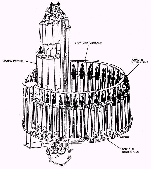
Figure 4-40.-Revolving magazine and screw feeder. nitrogen charge in the accumulator keeps a constant preestablished head of pressure in the system. The accumulator is connected to a pressure gauge and has a safety valve to prevent damage from overpressures on the system. BYPASS VALVE ASSEMBLY The bypass valve assembly reduces the starting load on the electric motor and the pump. As the motor starts, the bypass valve ports the pump output to the tank until the motor reaches operating speed. When the motor and the pump are shut down, the bypass valve automatically dumps the accumulator pressure to the hydraulic oil tank. |
 
|
|
|
||