| Tweet |

Custom Search
|
|
 
|
||
|
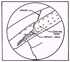
Distortion. - Heavy impact damage to the leading edge of the blade usually results in distortion. When the impact is severe enough, cracking and/ or tearing of the leading edge, adjacent to the impact area, occurs.
Figure 2-26.- HP turbine blade flaking and buildup. Record the magnitude and span location relative to the number of gill holes spanned. Estimate the out of contour as percent of the leading edge frontal area width or relative to the lateral spanning of the leading edge cooling hole rows. Blade Tip Nibbling.- The HP turbine rotor stage 1 blade tip nibbling is associated with hot running engines. Momentary overtemperature operation (such as experienced during compressor stalls) has exhibited this type of deterioration. This area of the blade is above the tip cap and located about two-thirds of the chord aft from the leading edge. Figure 2-27 shows a typical "nibbled tip" as a result of a severe stall.
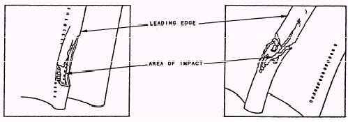
Blade Leading Edge Impact Damage.- Figures
2-28 and
2-29 show an impacted and distorted leading edge of a stage 1 HP
turbine rotor blade. (Note the cracking condition leading from the
impact area into the airfoil surface.) The critical part of this type of
damage is the axial or chord wire cracking. If this cracking progresses
from the impacted damaged area into the
Figure 2-27.- HP turbine blade tip nibbling. convex or concave airfoil surface, the damage can be severe. HP Turbine Blade Coating Failure.- The HP turbine protective coating is the key factor in the service
Figure 2-28.- HP turbine blade impact damage. life of an LM2500 GTE. The combined effect of film cooling and protective coating will extend the service life. Coatings are thinly and uniformly applied by a vacuum film deposition process. Coatings do not usually cause problems by chipping, peeling, or flaking. The normal failure mode is usually by pitting, rub off, or nicks and scratches. Occasionally a bubble will occur in the surface coating during the coating process. If a bubble occurs, it will be tested at the coating facility to ensure that it cannot be rubbed off the surface. These bubble imperfections pose no problem to the engine. If the bubble area of the coating fails, you should monitor that area to determine any further deterioration. Development and testing of new coatings that are highly resistant to corrosion and erosion are in progress. The present blade coating for single shank HP turbines is designated BC23. However, twin shank HP turbine
Figure 2-30.- HP turbine rotor stage 1 blade- areas of severe corrosion after extensive operating time. blading presently have blade coating BC21. As they become serviceable by an area Naval Aviation Depot (NADEP) these blades will be replaced with blades coated with BC23. Use of these newer blade coatings can significantly extend blade service life. HP TURBINE BLADE FAILURE MODES.- Failures that you may observe during a borescope inspection include the following types: l Corrosion of the coating. This appears as pitting of the coating primarily in the 80-percent span midchord region of the concave airfoil (thumbprint) side and the 20-percent span midchord region (root print) (fig. 2-30). This corrosion/ erosion has not been found on blades coated with BC23.
Figure 2-29.- HP turbine leading edge impact damage. Cracks in all areas of the blade, including radial cracks in the tips. Cracks generally start at the cooling holes. FOD/ DOD, including nicks and dents. Aluminum spattering that appears as metallic deposits on the blade. This results from compressor tip rubs. HP turbine blade tip rubs. This results in coating removal and tip damage. |
 
|
|
|
||
|
|
Integrated Publishing, Inc. - A (SDVOSB) Service Disabled Veteran Owned Small Business
|