| Tweet |

Custom Search
|
|
 
|
||
|
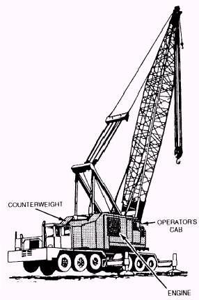
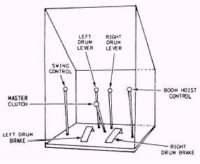
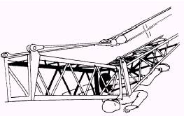
Bridle Assembly The bridle assembly is part of the boom suspension system and is sometimes called a floating harness. The bridle assembly may be connected to the boom mast or as a floating harness on a crane equipped with a gantry. The bridle assembly is the connection point for the boom pendant lines and is an assembly of sheaves in which the boom hoist wire rope reeves through. Boom Stops Boom stops are designed to prevent the boom from going over backwards in case a load line breaks. They will not stop the boom if the operator forgets to disengage the boom hoist control lever. However, some models of cranes are equipped with a boom upper limit switch that prevents the operator from raising the boom past a preset boom angle. This switch also prevents operators from raising the boom into the boom stops. Most cranes that are equipped with the upper limit switch also have a bypass switch that allows the operator to raise the boom past the preset boom angle. Two types of boom stops are shown in figures 12-18 and 12-19. House Assembly The house assembly is a revolving superstructure that sets on top of the carrier frame (fig. 12-20). It provides a mount for the hoist mechanisms and engine and is sometimes called the machinery deck. The operator's cab and counterweight are attached to the home assembly. OPERATOR'S CAB.- The control levers for a lattice boom crane are located in the operator's cab. The control levers that are shown in figure 12-21 are typical of most cranes. Typical crane controls areas follows: 1. The swing lever, when pulled towards you, rotates the house assembly in one direction, and when pushed, the house assembly rotates in the opposite direction.
Figure 12-20.-House assembly.
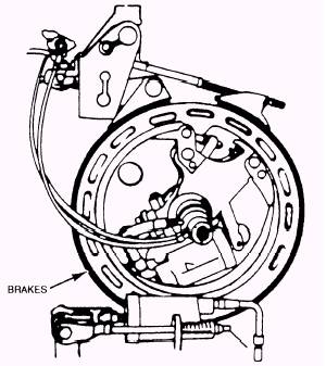
Figure 12-21.-Lattice boom crane control levers. 2. The left drum brake pedal is used to hold and lower loads placed on the hoist line. When locked, it prevents the hook block and wire rope from unwinding on the hoist drum. Figure 12-22 shows a typical hoist brake assembly.
Figure 12-22.-Hoist brake assembly. 3. The main drum lever engages power to raise and, on some models, support lowering of loads placed on the main hoist drum. 4. The master clutch engages the power from the power source to the hoist and swing mechanisms. 5. The secondary drum lever engages power to raise and, on some models, support lowering of loads placed on the secondary hoist drum. 6. The right drum brake pedal is used to hold and lower loads placed on the hoist line. When locked, it prevents the hook block and wire rope from unwinding on the hoist drum. 7. The boom hoist lever allows for the raising and lowering of the boom. HOISTING MECHANISM.- The hoisting mechanism provides the mechanical power to lift and lower loads. The hoisting mechanism usually has two hoist drums that are mounted side by side on one shaft or in tandem. A separate clutch and brake controls each hoist. The control levers, operating the clutches and brakes, are normally power-assisted with hydraulics or air pressure. A lifting operation requires the use of one drum; whereas the clamshell, dragline, and pile-driving operations require the use of two. ENGINE.- The engine provides power to the hoisting mechanism through a gearbox or, in some cases, a drive chain reduction. In most lattice boom cranes, the engine is mounted in the crane house. COUNTERWEIGHT.- The counterweight on the rear of the crane house creates additional stability when lifting loads. The counterweight rotates with the house as it swings. Most counterweights are removable to reduce the overall weight of the crane for transporting. Part of your prestart inspection is to check the counterweight mounting.
Figure 12-24.-Never work under a crane boom. |
 
|
|
|
||