| Tweet |

Custom Search
|
|
 
|
||
|
COMPONENTS Oil-free reciprocating air compressors use a crosshead arrangement consisting of a guide piston and cylinder and guide piston seal assembly. The design separates the compressor section from the running gear section and still transfers mechanical power from the lubricated crankshaft to the piston and connecting rod assemblies of the nonlubricated compressor stages. Refer to figures 14-14 and 14-15 as we continue. The compression piston is hollow and is connected to the guide piston by the guide piston seal assembly. (Refer to fig. 14-14.) The piston rings are made from a Teflon-bronze material that will become damaged upon contact with lube oil. The guide piston seal assembly contains oil control rings and seal rings, retainer rings, a cup, and a cover. (See fig. 14-15.) The seal assembly prevents oil from entering the compression chamber by scraping the oil from the piston connecting rod as it moves up and down in the seal assembly. The running gear chamber consists of a system of connecting rods, a crankshaft, and a flywheel. (NOTE: The connecting rods are connected to the guide piston in the oil-free air compressor.) The valve assemblies are of the strip/feather type previously discussed in this chapter. UNLOADER SYSTEM The Worthington oil-free, low-pressure air compressor unloader system consists of three suction valve unloaders, one for each cylinder, connected to each suction valve assembly. (See figs. 14-16 and 14-17.) The major components of
Figure 14-14.-Cutaway view of an oil-free, low-pressure air compressor.
Figure 14-15.-Guide piston seal assembly.
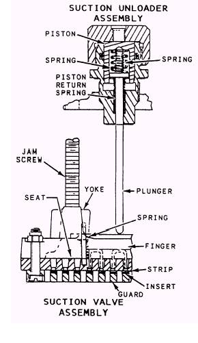
Figure 14-16.-Suction unloader and valve assembly.
Figure 14-17.-Unloader system of an oil-free, low-pressure air compressor.
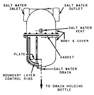
Figure 14-18.-Moisture separator. the unloader assembly are the piston, springs, and plunger. (See fig. 14-16.) The unloader assemblies are actuated by a single solenoid-operated valve that routes the air from the receiver to the top of the piston in the suction unloader assembly. Air pressure forces the piston down, thereby forcing the finger down against the strip valves and unseating the suction valves. This action causes the air compressor to be in an unloaded condition when the drive motor starts. The compressor becomes loaded when the solenoid-operated valve bleeds the air off the top of the piston in the unloader assemblies through the flow control valve. The pistons and fingers are forced upward by the piston return spring, causing the suction valves to seat. The flow control valve prevents instant full loading of the compressor by controlling the amount of airflow from the unloader assemblies through the solenoid-operated valve. The oil-free air compressor has a moisture separator that receives air from an air cooler. (See fig. 14-18.) The separator drains the collected
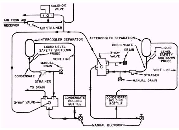
Figure 14-19.-Condensate drain system. moisture into a drain holding bottle where the moisture is then removed by either the automatic drain system or the manual drain valves. The separator has a level probe that shuts off the air compressor in the event that the drains are backed up because of a malfunction of the automatic drain sys-tem. The automatic drain system uses a solenoid-operated valve and a three-way air-operated valve. (See fig. 14-19.) The solenoid-operated valve is energized by a time relay device in the motor controller. The solenoid-operated valve admits air to the three-way air-operated valve, which allows for drainage of the moisture separator and the holding bottle. |
 
|
|
|
||