| Tweet |

Custom Search
|
|
 
|
||
|
ROTARY
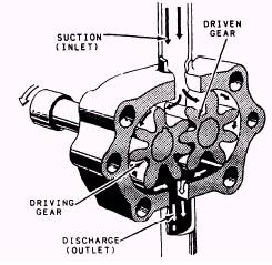
PUMPS The operation of a positive-displacement rotary pump depends upon the principle that rotating gears, vanes, screws, or lobes trap liquid in the inlet side of the pump casing and move it to the outlet connection-thus producing flow. (POSITIVE DISPLACEMENT means that a definite quantity of liquid is moved from the inlet to the outlet side on each revolution.) In a positive displacement pump, pressure is the result of RESISTANCE TO FLOW in the system to which it discharges. Pressure is limited only by the bursting strength and available power of the pump. For this reason, relief valves are always fitted on the pump discharge. Positive-displace-ment rotary pumps have largely replaced recipro-cating pumps for pumping viscous liquids in naval ships, as they have a greater capacity for their weight and occupy less space. Rotary pumps have very small clearances be-tween rotating parts to minimize slippage (leakage) from the discharge side back to the inlet of the pump. With close clearances, these pumps must be operated at relatively low speeds to obtain reliable operation and maintain capacity over an extended period of time. Types of Rotary Pumps There are several types of positive-displace-ment rotary pumps, including the simple gear, herringbone gear, helical gear, vane, lobe, and screw types. The main features of gear and screw pumps will be discussed briefly in the following paragraphs. SIMPLE GEAR PUMP.-The simple gear pump (fig. 13-1) has two spur gears which mesh
Figure 13-1.-Simple gear rotary pump. together and revolve in opposite directions. One is the DRIVING GEAR, and the other is the DRIVEN GEAR. Clearances between the gear teeth (the outside diameter of the gear) and the casing, and between the end face and the casing are only a few thousandths of an inch. As they turn, the gears unmesh and liquid flows into the pockets which are vacated by the meshing gear teeth. This creates the suc-tion that draws the liquid into the pump. The liquid is then carried around in the pockets formed by the gear teeth and the casing. At the outlet, or discharge side, the liquid is pushed out (dis-placed) by the meshing of the gear teeth and is forced to flow through the outlet connection of the pump. HERRINGBONE GEAR PUMP.-In the herringbone gear pump (fig. 13-2), a modifica-tion of the simple gear pump, one discharge phase begins before the previous discharge phase is entirely complete. This overlapping tends to give a steadier discharge pressure than is found in the simple gear pump. Power-driven pumps of this type are sometimes used for low-pressure lubricating oil service and fuel service. |
 
|
|
|
||