|
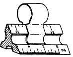
Triangular Scale Clip For use with a triangular scale, a scale clip or scale
guard, such as the one shown in figure 2-27, is
very helpful. The clip makes it easy for you to identify
what scale you are using. Large spring-type paper
clips will serve the same purpose when scale
clips are not available.

Figure 2-27.-Use of triangular scale
clip.
MAP MEASURES AND SCALE
INDICATORS
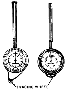
MAP MEASURES are precision instruments for
measuring the lengths of roads, pipelines, and other
irregular outlines on maps and drawings. Distances
are measured by first setting the instrument
to zero, then tracing the line to be measured
with the small, projecting tracing wheel, like
that on the map measures shown in figure 2-28.
In using map measures, do not depend entirely on
the indicated numerical scale. Always check it
against the graphical scale on the map or drawing.
Verify if, for example, 1 in. traversed

Figure 2-28.-Types of map measures.
on the graphical scale really registers 1 in. on the dial;
if not, make the proper correction to the distance
measured. Actually, a map measure is just
another odometer. Odometers are used to measure
actual distances, while the map measures are
used to measure scaled distances. There
are many ways of indicating the scale on
a drawing. Among these are the fractional method,
the equation method, and the graphic method.
In the fractional method, the scale is indicated as
a fraction or a ratio. A full-size scale is indicated
as 1/1; enlarged scale, as 10/1, 4/1, 2/1, etc.;
and reduced scale, as 1/2, 1/4, 1/10, etc. Notice
that the drawing unit is always given as the
numerator of the fraction and the object unit as
the denominator. On maps, the reduced scale fraction
may be very large (for example, 1/50,000),
as compared with the typical scales on
machine drawings. On maps, the scale is frequently
expressed as a ratio, such as 1:50,000. In
the equation method, a certain number of inches
on the drawing is set equal to a certain length
on the object. Symbols are used for feet (')
and inches ("). On architectural drawings, a certain
number of inches on the drawing is set to equal
to 1 foot on the object. A full-size scale is
entered as 12" = 1' 0"; an enlarged scale, as 24"
= 10"; and a reduced scale, as 1/8"
= 1' 0". On civil engineering drawings, 1 in.
on the drawing is set to equal to a certain measurement
on the object: 1" = 5', 1" = 100', 1"
= 1 mi.
In the graphic method, an actual measuring scale
is shown on the drawing. Typical graphic scales
are shown in figure 2-29. Note that in each case,
the primary scale lies to the right
of the 0; a
subdivided primary scale unit lies to the left
of the
0.
|


|

