TM 5-4240-501-14P
SYNCHRO-BALANCE
Oscillating Counterbalance
Remove counterweight from the shaft.
Fig. 9 - Disassembling Counterweight
ASSEMBLY
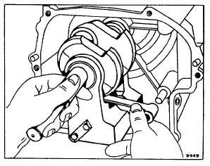
Assemble magneto side of counterweight to the magneto
side of the crankshaft. Hold the crankshaft and
counterweight in an upright position in a vise. Install both
dowel pins. Slip link over dowel pin with rounded edge of
free end up. Fig. 10.
NOTE: New style counterweight assemblies use only
one (1) dowel pin, one (1) spacer, and one (1) bolt. No
lock is required. Torque to 115 in/lbs. (1.32 mkp or 13.0
Nm).
Fig. 10 - Assembling Counterweight to Crankshaft
Slip PTO counterweight in place, aligning counterweight
bearing to the eccentric of crankshaft and against
magneto half of counterweight. Install spacers and
torque bolts to 80 inch-pounds (.9 mkp or 9.0 Nm). Bend
up bolt locks and install crankshaft gear (and key on
MODEL SERIES 171700). Gear is a slip fit - if tight, it
may be heated to expand by laying it on a light bulb.
NOTE: Chamfer on inside diameter of gear must face
shoulder of crankshaft.
Lay cylinder on its side with cylinder head to the left.
Start magneto journal of crankshaft into the magneto
bearing in the cylinder. Align the link with the crankcase
link
pin
and
push
crankshaft
and
counterweight
assembly into place. Fig. 11.
Fig. 11 - Installing Crankshaft and Counterweight
Assembly
Install connecting rod and piston with lubrication hole in
rod toward magneto side. This will expose rod assembly
marks to view. Assemble the cap screws and screw
locks with dipper toward cam gear side. Torque screws
and bend up locks. Proceed to install tappets. cam
gear. etc.. in usual manner.
Table No. 1
Crankshaft Eccentric Reject Sizes
Basic Model Series
Eccentric
‘
Inch
Milllmeter
171700 & 191700
1.870
47.50
251700 & 252700
2.120
53.85
Counterweight Bearing Reject Sizes
Basic Model Series
Counterweight Bearing.
Inch
Milllmeter
171700 & 191700
1.881
47.78
251700 & 252700
2.131
54.13
4