ALTERNATOR
4 Amp
Fig. 201 - Rectifier Plug
Testing Stator
If “short” test indicates stator is shorted, look for obvious
shorts on leads. If bare leads are found, repair with
friction tape and shellac. If shorted leads are not visible,
replace stator. Stator should also be checked for
continuity as follows: Use VOA meter, set on resistance
scale. Touch one test prod to lead at fuse holder. Touch
other test prod to each of the four pins in plastic
connector. See Figure 202. Unless the meter shows
continuity at each of the four pins, .the stator winding is
open and the stator must be replaced.
Fig. 202 - Testing Stator
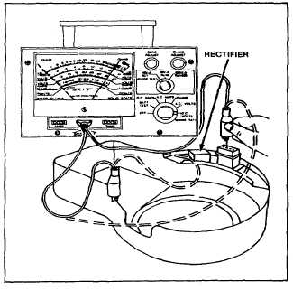
Testing Rectifier
Attached to the blower housing baffle is a small black
rectifier box. A lead from the box connects to a single
pin in the detachable plug. See Figure 201. Leave box
installed on blower housing. Test rectifier with
multimeter (using resistance scale) to check resistance
from the pin to blower housing (in an unpainted clean
area). See Figure 203. After checking pin, reverse
meter leads and recheck. The meter should show a
reading in one direction only: If the rectifier pin shows a
meter reading both ways, the rectifier is defective. If the
pin shows no reading either way, the rectifier is again
defective.
Fig. 203 - Testing Rectifier
Testing Alternator Output
Install ammeter in series with charging lead, as in Figure
204. Start engine. Ammeter should indicate charge.
If ammeter shows no charge, and if rectifier has been
tested, look for loose connections, broken or frayed
wires, etc. If there is no visible fault, replace stator and
re-test alternator output.
Fig. 204 -- Testing Output
63