
TM 11-6130-247-14-1
d. Troubleshooting Chart.
Malfunction
Probable cause
Corrtrol action
I
1. VOLT MODE and CUR MODE indicators
Defective lamp. . . . . . . . . . . . . . . . . . . . . .
Determine mode of operation and replace ap-
not lit.
propriate lamp.
a. Shorted di?? main rectifier CR1-CR4
2. Fuse F1 blown . . . . . . . . . . . . . . . . . . .
a. Replace defective diode,
b. Defective switching stage Q? and Q10 . . .
b. Replace defective component.
c. Filter capacitor C1, C2, or C13 shorted . .
c. Replace defective component.
d. Defective passing stage Q13, Q14 or Q15.
d. Replace defective component.
.....
a. Open PAR OPER. terminals (between
a. Check wiring for open or loose link.
3. Low output or no output voltage. . . .
pins 10 and 11 on TR1)
b. Replace switch.
b. Switch S1 defective......
c. See 2 above.
c. Fuse F1 blown . . . . . . . . . . . . . . . . . .
d. Replace defective component.
d. Defective switching stage Q9 and Q1O
e. Replace defective component.
e. Defective Schmitt trigger A4Q5 and
A4Q6.
f. Replace transformer.
f. Defective transformer T1 . . . . . . . . . . . .
a. Open SENSE connection . . . . . . . . . . . . .
4. Highoutput voltage . . . . . . . . . . . . . . . .
a. Check wiring for open or loose link.
b. Check oscillator frequency and adjust if
potentiometer A4R4 misadjusted.
required.
c. Defective Schmitt trigger A4Q5 and
c. Replace defective component.
A4Q6.
d. Replace defective component.
d. Voltage regulation circuits A3Q36,
A3Q35, A3Q33, or A3Q32 defective.
e. Defective VOLT ADJ potentiometer
e. Replace defective component.
R59A or R59B.
f. Preregulator control potentiometer
f. Replace defective unit and readjust pre-
A3R57 or amplifier A3Q20 defective.
regulator.
5. No current limiting . . . . . . . . . . . . .
a. Check and tighten if necessary,
a. Loose connection at CUR PROG termi-
nals.
b. Replace defective component.
b. Defective CUR ADJ potentiometer R53A
or R53B.
c. Replace defective component.
c. Defective balance adjust potentiometer
A3R50.
d. Replace defective component.
d. Current regulation circuit A3Q18,
A3Q19, A3Q16, or A3Q17 defective.
e. Replace defective component.
e. Defective temperature compensation net-
work A4Q38, A4C41, R28, or A4R99.
NOTE. Overcurrent protection check (para
5-9) must be accomplished if A4Q38 or R28
is found to be defective.
5-5. Initial Settings for Adjustments
a. Remove screws holding one-piece top and side
cover from power supply, exposing interior of power
supply.
b. Set printed board potentiometers A4R4, A3R50,
and A3R57 to their midpoint positions.
c. Set front panel CUR ADJ fine and coarse control
potentiometers R53A and R53B and VOLT ADJ
coarse and fine control potentiometers R59A and
R59B to the midpoint position.
d. Set internal potentiometers R54 and R69 to their
midpoint positions.
e. Be sure that terminal board links are connected
as stated in paragraph 2-5a.
f. Connected load (variable resistor 5- to 50-ohm, 200-
watt) to power supply front panel binding posts. Set
variable resistor to midposition.
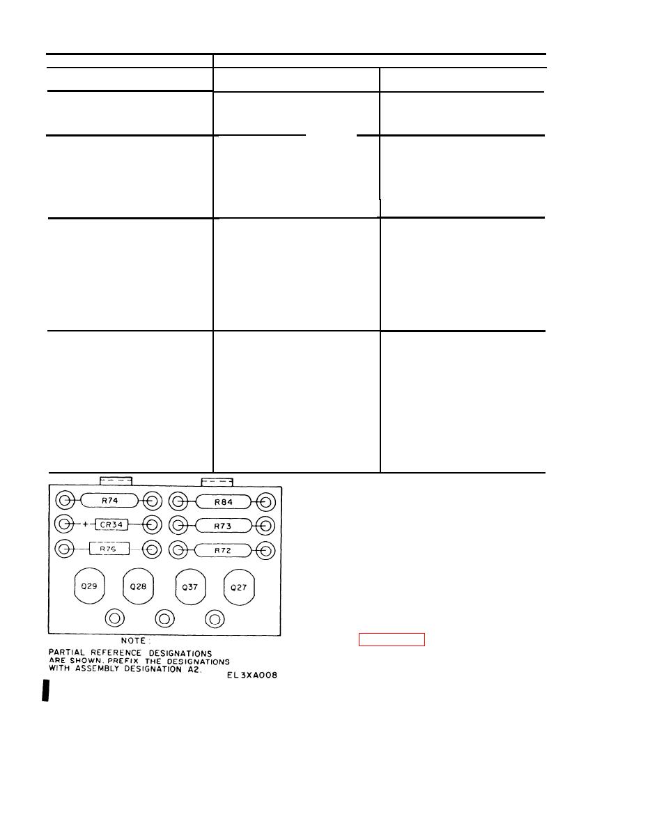
Figure 5-2 Power Supply PP-3940A/G, Component Board A2,
g. Connect power supply to variable power trans-
Parts Location Diagram.
former (TF-171A/U).
Change 1
5-2

