
TM 9-4120-411-14
4.9 LOGIC CONTROL DETAILS - CONTINUED.
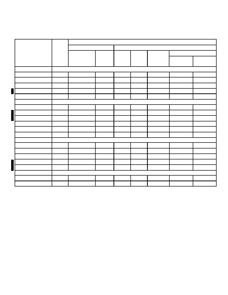
Table 4-2. LED Condition For Normal Operating Modes.
CLIMATE CONTROL
COOL
HEAT
LOW AMB
LOW
1st
2nd
1st
2nd
LED
VENT
NORMAL
AMB
STAGE
STAGE
DEFROST
STAGE
STAGE
STATUS
CI T (D30)
COOL (D35)
HEAT (D34)
RH 1 (D33)
DEF (D31)
SSR
RV (D17)
RH 2 (D19)
RH 1 (D20)
BLOW (D21)
COMP (D22)
FAN (D23)
FEEDBACK
COMP ON (D3)
BLOW ON (D4)
FAN ON (D5)
RH 1 ON (D6)
RH 2 (ON) (D11)
CONTROL PANEL
(VENT) ON
(CLIMATE) ON
Note: A dot " " on the table indicates the LED is ON.
Several components operate under a time delay of between one second to three minutes depending on the
component or operating condition. If an LED is not on, but should be, wait until all time delays have reset. Note
that a control logic time-out circuit may prevent the unit from operating immediately. If this occurs, do not turn the
unit off, it should start automatically within 5 minutes.
The REM (D12) LED will be on if using the remote panel for control and additional LED's are used to indicate faults
in the system.
Status LED's serve two additional functions; they indicate, in binary code, the settings of on board temperature
potentiometers and TP 1 terminal point if a major or minor failure occurs.
In CLIMATE CONTROL mode, the blower will operate continuously if using THIS BOX (local) control panel but will
cycle with heating or cooling demand if using REMOTE PANEL for control.
4-22 Change 1

