
TM 9-4120-408-14
PROCEDURES:
a. Refer to Figure H-2 and determine faulty wire.
b. Remove and discard cable clamp adapter (Figure F-2, 2), insulation sleeving (3), and insulation sleeving
(9) from connector (1) and wiring.
c. Remove faulty wire from wiring harness.
d. Refer to table F-4 to determine wire and cut wire to dimensions shown in Figure F-2.
e. Refer to tables F-3 and F-4 to assemble wire. Mark wire with from to termination designations and double
headed arrow on each end of wire assembly.
f. Install wire in connector (1).
g. Install new cable clamp adapter (2), insulation sleeving (3), and insulation sleeving (9), as shown in figure
F-2, and heat shrink to a firm fit.
h. Install tiedown straps at 3.00 inch maximum intervals and at each breakout.
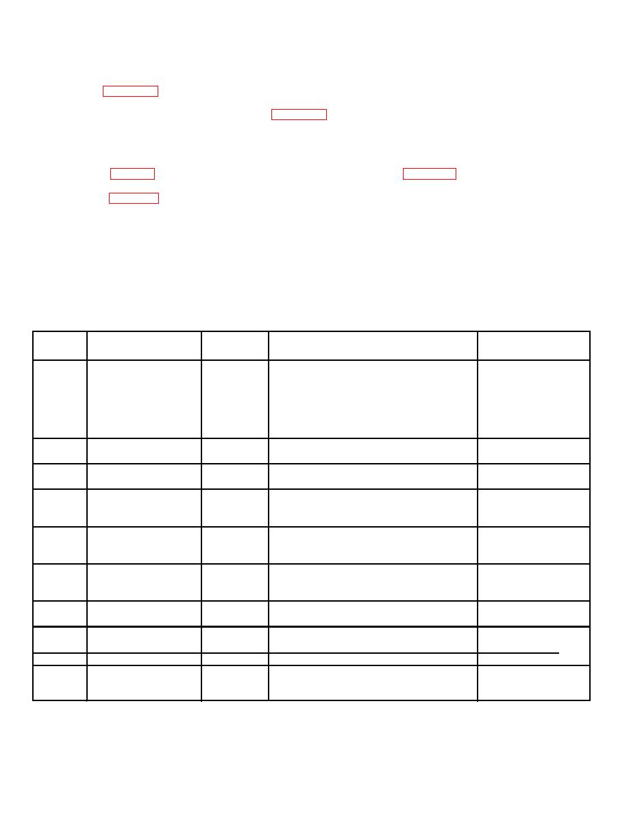
Table F-3. Parts List for Wiring Harness A104J2.
Find
Part or Identify-
Quantity
Description
NSN
Number
ing Number
Required
1
MS3450L2016S
1
Connector, Recepta
5935-01-066-0851
cle, Electrical, Box
Mounting, Rear
Release, Crimp
Contact, AN Type
2
M85049/601W20
1
Adapter, Cable Clamp
5935-01-228-1812
3
MS310906AC
1
Insulation Sleeving
4
M5086/1129
AR
Wire, Electric,
Copper Conductor,
600 V
5
M5086/1169
AR
Wire, Electric,
Copper Conductor,
600 V
6
13230E44552
1
Terminal, Quick
Disconnect, Female
900
7
MS25036112
2
Terminal, Lug, Crimp
5940-00-143-4794
Style
8
MS25036108
5
Terminal, Lug, Crimp
Style
9
M23053/51070
AR
Insulation Sleeving
5970-00-954-1624
10
MS336759
AR
Strap, Tiedown,
5975-00-111-3208
Electrical
F-5

