
TM 9-2330-357-14&P
5-12. OUTRIGGER DRIVE MOTOR THERMAL SWITCH REPLACEMENT (Con't).
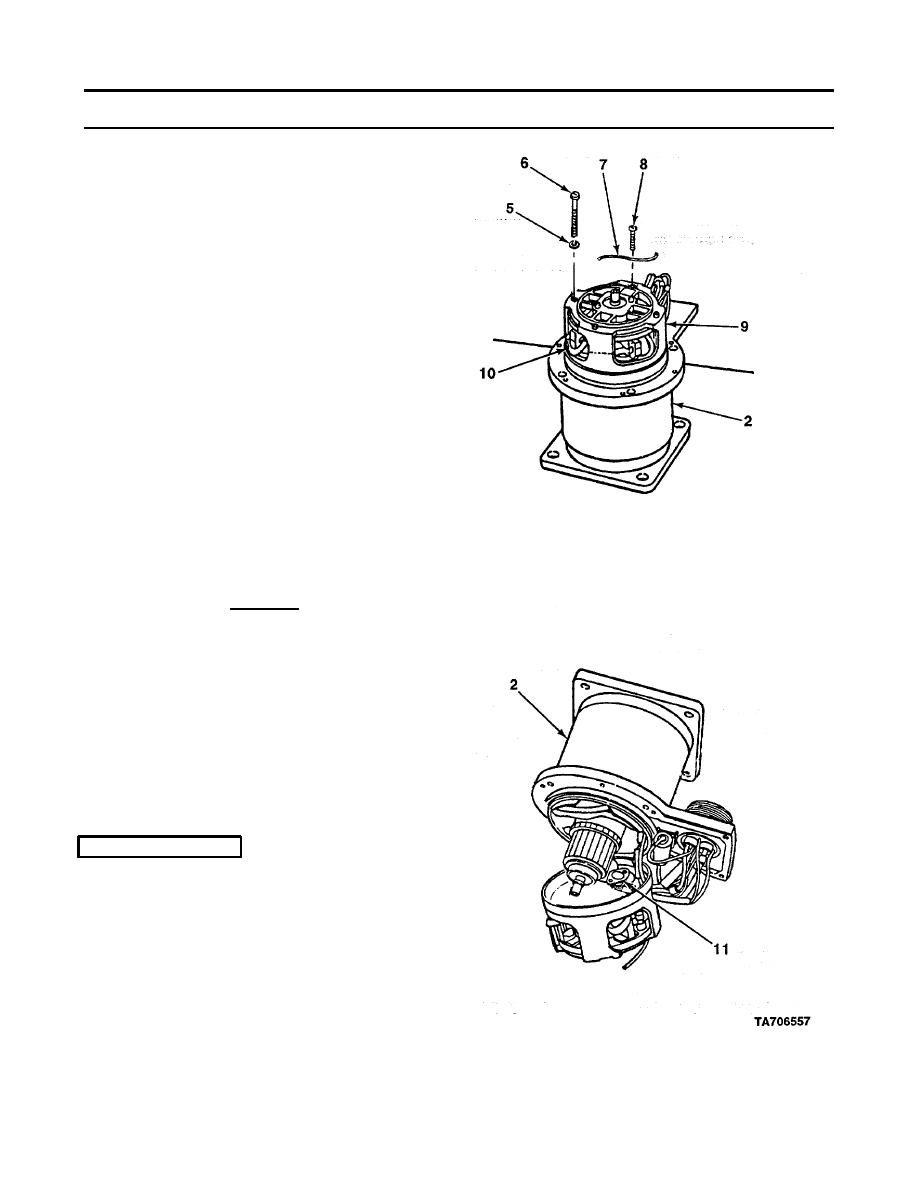
NOTE
DO NOT remove ground brush screws.
6.
Pull four brush es (10) from brush holders until
brush spring moves to side of brush.
7.
Remove screw and disconnect field positive
lead wire from side of electrical switch.
CAUTION
DO NOT allow washers and nuts to drop
inside outrigger drive motor. Outrigger drive
motor will have to be replaced if they cannot
be recovered.
8.
Remove two screws, washers, and nuts which
hold thermal switch (11) in place against rear
of outrigger drive motor housing (2).
9.
Unsolder two wires, which come from pin E
and pin F to thermal switch (11) (TB SIG 222).
b.
INSTALLATION
1.
Solder two wires from pin E and pin F to
thermal switch (11) (TB SIG 222).
2.
Install thermal switch (11) against rear of
outrigger drive motor housing (2) with two nuts,
washers, and screws.
3.
Connect field positive lead wire to side of
electrical switch with screw.
5-51

