|
| |
TM 9-2330-398-24
3-10. BOGIE ASSEMBLY REPLACEMENT (continued).
3.
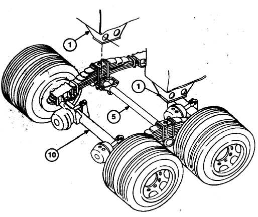
Position two jacks under trunnion tube (5) close to inside of each trunnion hanger (4). Raise jacks to support
weight of trunnion tube (5).
4.
Remove eight self-locking nuts (6) and screws (3) from trunnion hangers (4) and two trunnion cross tube mounting
brackets (1). Discard self-locking nuts.
5.
Lower and remove jacks from under trunnion tube (5).
6.
Using lifting device, raise semitrailer until it clears bogie assembly (10).
7.
Manually release brake air chambers (para 2-60).
8.
Roll bogie assembly (10) out from under rear of semitrailer.
9.
Lower semitrailer onto supports or cribbing.
b.
INSTALLATION
1.
Using lifting device, raise rear of semitrailer high enough to allow bogie assembly (10) to roll under rear of
semitrailer. Remove supports or cribbing.
2.
Roll bogie assembly (10) into position under mounting brackets (1) and trunnion hangers (4) on each end of
trunnion tube (5).
3.
Manually set brake air chambers (para 2-60).
3-33
|