|
| |
TM 10-4930-247-13&P
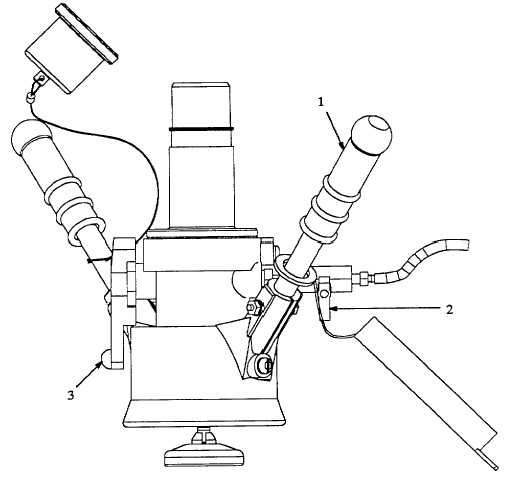
2-2. RECIRCULATION NOZZLE.
Refer to figure 2-2.
Locking Handles (1).
Two locking handles on the nozzle body aid positioning and connection of the nozzle to the HEMTT tanker
refueling adapter. The nozzle is positioned on the tanker refueling adapter and the handles are turned to the right
to connect the nozzle; left to disconnect.
Ball Valve (2).
The ball valve is used to take samples of fuel being recirculated in the HTARS. To obtain a fuel sample, turn the
control handle to the left. When enough fuel has been obtained, turn control handle all the way to the right to stop
fuel flow.
Control Lever (3).
The control lever has two positions, OPEN and CLOSE. When the nozzle is connected to the aircraft refueling
adapter, rotating the crank handle to OPEN allows fuel flow through the nozzle. When set to CLOSE, fuel flow is
stopped. Mechanical locks prevent setting the crank handle to OPEN when the nozzle is not connected or
disconnecting the nozzle before the lever is set to CLOSE.
Figure 2-2. Recirculation Nozzle Controls.
2-3
|