|
| |
TRUCK SERVICE MANUAL
TM 5-4210-230-14&P-1
force carrier from housing, in some instances it may be
necessary to break carrier loose from axle housing by striking
the carrier with a heavy soft hammer (lead, plastic, rubber or
leather). Be sure that the differential is securely supported on
a portable floor lift before it is separated from the housing.
DISASSEMBLY
Mount differential assembly in a suitable holding fixture.
Remove Differential and Drive Gear Assembly
1. Remove cotter pins from bearing adjuster locks
and remove locks from bearing caps, Fig. 9.
Fig. 9 Adjuster Lock Removal
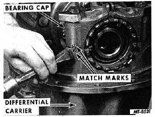
2. Match mark one differential bearing cap and leg
of carrier with punch or chisel, Fig. 10, to identify
each for correct reassembly.
Fig. 10 Marking Bearing Cap for Identity
3.
Remove bearing cap stud nuts or cap screws and
take off the bearing caps and adjusting nuts.
4.
Tip differential away from pinion and lift assembly
out of the differential housing, Fig. 11.
Fig. 11 Lifting out Differential and Gear Assembly
Disassemble Differential Case and Gear Assembly
1.
Match mark differential case halves, Fig. 12, with a
punch for correct alignment on reassembling.
Fig. 12 Marking Differential Case Halves
2.
Cut lock wire and remove capscrews or stud nuts to
separate case halves, Fig.13.
NOTE
Some differential assemblies use self-locking
capscrews and nuts.
3.
Remove spider, pinions, side gears and thrust
washers, Fig. 14.
4.
To remove drive gear rivets, carefully center punch
each rivet head. Next use a drill .8 mm (1/32")
smaller than body of the rivet and drill through rivet
head, Fig. 15. Use a
CTS-2095S-CHAPTER I-Page 6
PRINTED IN UNITED STATES OF AMERICA
|