
TM 5-3810-306-34
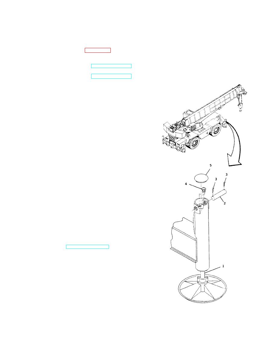
OUTRIGGER CHECK VALVE INSTALLATION
TOOLS: General mechanic's tool kit: automotive (5180-00-177-7033)
SUPPLIES:
Cotter pins (Item 10, Appendix B)
EQUIPMENT CONDITION: Hydraulic pressure relieved from system.
(Refer to TM 5-3810-306-20.)
Negative battery cable disconnected at shunt.
(Refer to TM 5-3810-306-20.)
REMOVAL:
1. REMOVE OUTRIGGER CHECK VALVE (4).
a. Position a suitable jack under jack cylinder and
raise to relieve pressure from pin (2).
b. Remove cap (5).
c.
Remove two cotter pins (3) and remove pin (2)
securing jack cylinder (1). Discard cotter pins
(3).
d. Loosen outrigger check valve (4) slowly to
relieve hydraulic pressure. Remove outrigger
check valve (4).
INSTALLATION:
1. INSTALL OUTRIGGER CHECK VALVE (4).
a. Install outrigger check valve (4) in jack cylinder
(1).
b. Install jack cylinder pin (2) through outrigger
body and jack cylinder (4). Secure with two new
cotter pins (3).
c.
Install cap (5).
2. CONNECT NEGATIVE BATTERY CABLE
AT
SHUNT. (REFER TO TM 5-3810-306-20.)
3. TEST FOR PROPER OPERATION.
END OF TASK
11-6

