
(10) Check inside diameter of front bushing (2). If
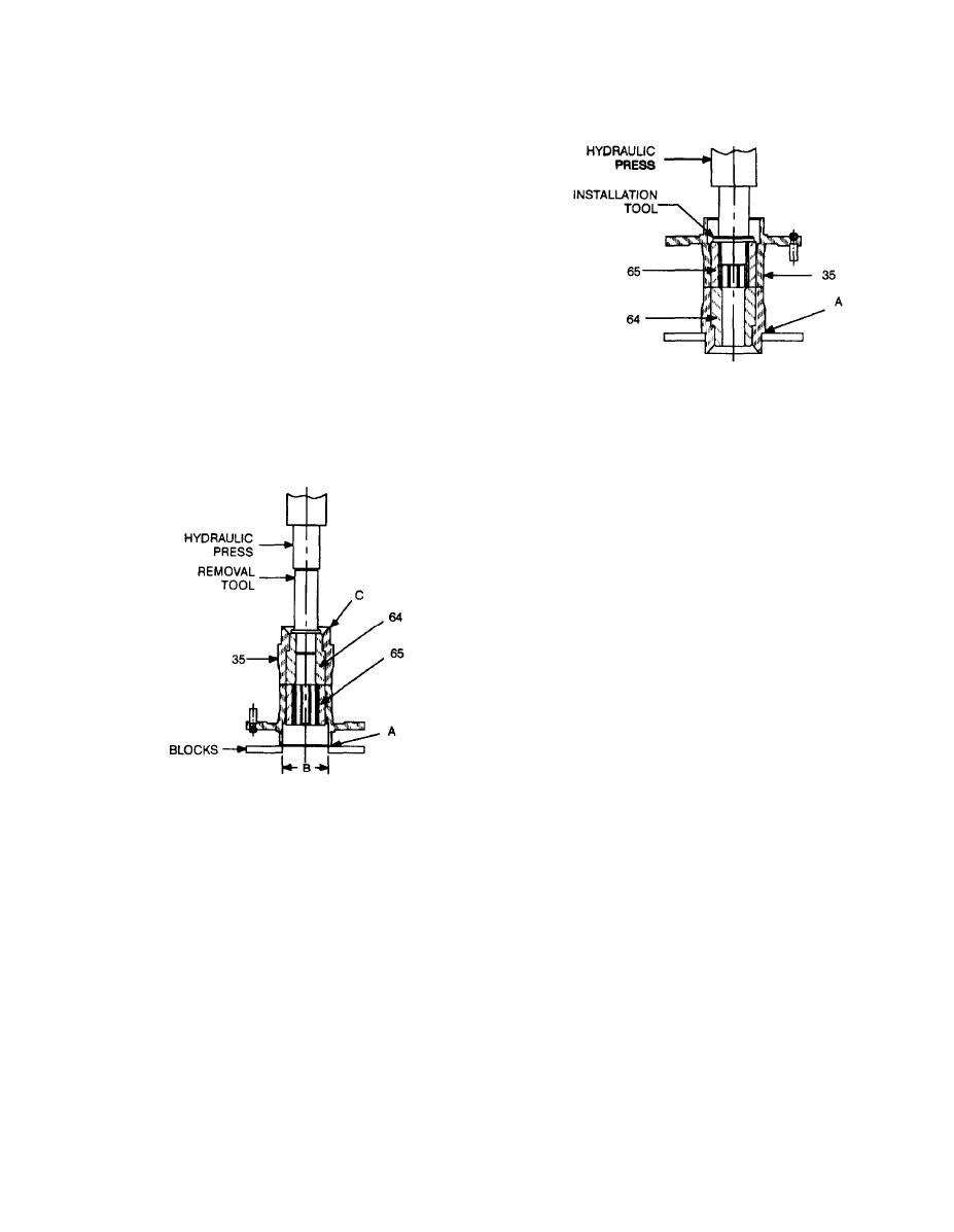
(c) Using fabricated installation tool, press
inside diameter is greater than 1.285 in., replace front
chuck driver (65) into carrier (35), using the minor diame-
bushing. If front bushing can no longer be kept tight be-
ter of the spline marks as a guide.
cause of excessive wear on inside face of front cap (1) re-
place cap.
(11) Check for wear on retainer (26) and both sides
of spring washer (27). Replace if worn.
(12) Inspect gland plug (4) for damage and wear.
Replace if damaged or worn.
(13) Inspect chuck bushing (64) inside carrier (35).
If striking bar imprint is 0.050 in. or greater, replace chuck
bushing (see step (16) below).
(14) Check inside diameter of chuck bushing (64). If
inside diameter is greater than 1.405 in., replace chuck
bushing (see step (16) below).
c. Assembly.
(15) Check splines on chuck driver (65). If splines
(1) Tap bearing cup (50) into main housing (51).
are worn half through, replace chuck driver (see step (16)
(2) Install new gasket (59) and cover (58) on main
below).
housing (51) using four screws (56) and new lockwashers
(16) To remove chuck bushing (64) or chuck driver
(57).
(65):
(3) Install new gasket (55) and manifold (54) on
main housing (51) using four screws (52) and new lock-
washers (53).
(4) Install grease fitting (60) in main housing (51).
(5) Press two shafts (37) into flange (38). Carefully
orient ends of shafts so that they will properly key into
slots in plate (39) when installed.
(6) Install gear (45) on each shaft (37).
(7) Place two bearings (41) and spacer (42) in be-
lower than surface of gears.
(8) Seat motor housing (40) on flange (38). Aline
two dowel pin holes and tap in two dowel pins (36).
(9) Install air motor gear (43) on flange (38).
(10) Install front plate (44) on dowel pins (36) and
shafts (37) and gently tap in place.
(a) Set carrier (35) in hydraulic press as shown.
(11) Press three shafts (48) into carrier (35). Install
End A should rest on blocks set far enough apart and deep
three nuts (49) and secure with thread-locking compound.
enough to allow clearance for the chuck bushing (64) and
(12) Press bearing cone (46) onto carrier (35).
driver (65) to be pressed through B. Do not attempt to
(13) Slide gear (47) onto each shaft (48).
press out parts with carrier resting on face C.
(14) Set carrier (35) face down and slide air motor
(b) Insert fabricated removal tool (see Appen-
assembly (31) onto carrier. Ensure gears mesh properly.
dix D) between press and chuck bushing (64) as shown.
(15) Press bearing cone (34) onto carrier (35).
(c) Press chuck driver (65) and bushing (64) out
(16) Install plate (39), outer edge bevel facing up, on
of carrier (35).
back of air motor assembly (31). Shafts (37) fit into slots
(17) To install chuck bushing (64) and driver (65):
on plate.
(a) Set carrier (35) in hydraulic press as shown.
(17) Pack roller bearing (32) in accordance with TM
Rest face A on blocks.
9-214 and install (small end up) on bearing cone (34).
(18) Install main housing (51) over air motor assem-
(b) Using fabricated installation tool (see Ap-
bly (31). Ensure that shafts (37) are positioned correctly
pendix D), press chuck bushing (64) beveled face up, into
and aline with relief holes in main housing.
carrier (35) until seated.
27

