| |
TM 10-3930-664-24
3.
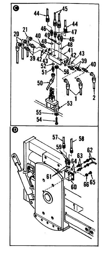
TAG AND DISCONNECT HOSE ASSEMBLIES
(1, 2, 20, 21, 44, 45, 50) FROM INTERMEDIATE
RAIL MANIFOLD (41).
4.
REMOVE INTERMEDIATE RAIL MANIFOLD
(41) AND ADAPTERS.
NOTE
Tension of hose assemblies (44, 45) is
determined by position of intermediate
rail manifold (24). Position of manifold
is adjusted by adding or subtracting
washers (56) between bracket and
manifold. When removing manifold,
record number of washers (55, 56)
between bracket and manifold and
between bracket and head of screw
(54). It is important that the same
number of washers are used during
installation.
a.
Remove intermediate rail manifold (41)
from inner rail by removing screw (54) and
washers (55, 56).
b.
Remove adapters (39, 40, 46, 47, 51) from
intermediate rail manifold (41).
c.
Remove and discard O-rings (42, 43, 48,
49, 52).
5.
DISCONNECT HOSE ASSEMBLIES (57, 58)
AND TUBE ASSEMBLIES (62) FROM SPINE
MANIFOLD (60). REMOVE SPINE
MANIFOLD AND ADAPTERS.
a.
Remove mud guard from sideshift
carrier by removing attaching screws,
washers, and spacers.
b.
Tag and disconnect hose assemblies (57,
58) from fittings (59).
c.
Remove fittings (59) from spine manifold
(60). Remove and discard O-rings (61).
d.
Tag and disconnect tube assemblies (62)
from adapters (63).
e.
Remove adapters (63) from spine
manifold (60). Remove and discard O-
rings (64).
f.
Remove spine manifold (60) from spine
assembly by removing screws (65) and
washers (66).
2-400
|