 |
|||
|
|
|||
|
|
|||
| ||||||||||
|
|
 TM 10-3930-660-24-1
TIRES REPLACEMENT - CONTINUED
0135 00
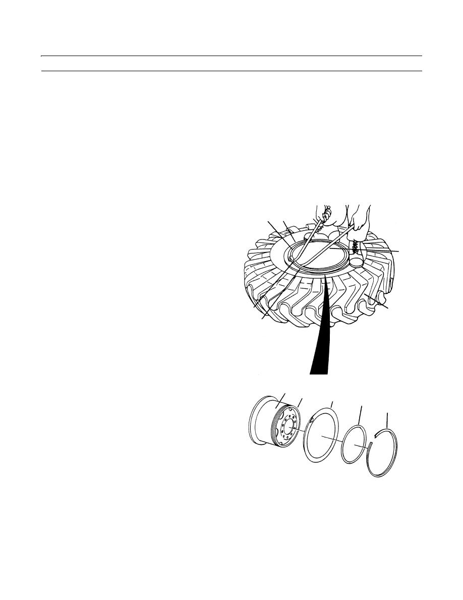
DEMOUNTING - CONTINUED
NOTE
The aligning ring encircles the lock ring which prevents unintended lock ring removal. An O-ring positioned
between aligning ring and rim (B) creates an airtight seal.
10.
Force outer tire bead and aligning ring (7) down towards center of wheel assembly (6) by standing on tire (3) and align-
ing ring (7).
11.
Remove lock ring (8) by inserting lock ring tire iron (C), curved side up, into prying notch (D) on lock ring (8) and gut-
ter of rim (B).
12.
Pry lock ring (8) out enough to insert flat tire iron (E), adjacent to tire iron (C), between lock ring (8) and base of rim
(B).
13.
Work both tire irons (C and E) progressively around
rim (B) until lock ring (8) is completely removed.
C
7
B
14.
With lock ring (8) removed, hold aligning ring (7)
down to remove and discard O-ring (9) from rim (B).
E
NOTE
If aligning ring becomes cocked on rim
(B), its removal will be difficult.
15.
Slide aligning ring (7) off rim (B) by lifting flange of
aligning ring (7) straight up.
D
3
8
6
B
7
9
8
409-4037
0135 00-3
|
|
Privacy Statement - Press Release - Copyright Information. - Contact Us |
