

TM 9-2350-222-20-1-4
SHIFTING CONTROL AND RELATED PARTS REPAIR AND REPLACEMENT
(Sheet 9 of 15)
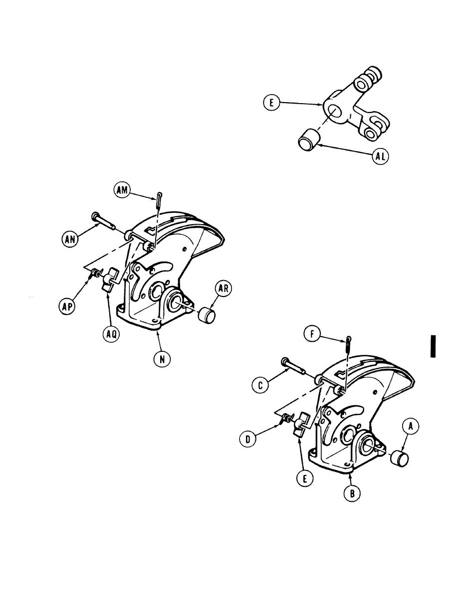
27. Using hammer and 3/8 inch punch, remove
bearing (AL) from connecting link (E). Throw
bearing away.
28.
Using pliers, remove cotter pin (AM). Throw
cotter pin away.
29.
Using pliers, remove pin (AN), spring (AP),
and hasp (AQ).
30.
Secure base assembly (N) in vise.
31.
Using brass drift and hammer, tap out
bearing (AR). Throw bearing away.
INSPECTION:
1.
Inspect all parts for damage and wear.
2.
Replace any damaged or worn part.
ASSEMBLY:
1.
Using vise with jaw guards, press new bearing
(A) in base assembly (B).
2.
Install pin (C) through spring (D) and hasp (E).
3.
Using pliers, install new cotter pin (F) in end of
pin (C).
GO on to Sheet 10
TA253380
Change 1
11-33

