
TB 9-2350-368-25
SECTION IV. COOLING SYSTEM
2-4.
salvaged from local can point or from DRMO. The recommended radiator is one taken from a 2-1/2 or 5-ton
truck. Any radiator will work if the radiator is mounted higher than the engine. Straight radiator hose with
fabricated elbows, and clamps for upper and lower connections will ease installation and removal. To prevent
any airlocks, the radiator must be mounted six inches above the top of engine. If weather is above 32,
antifreeze is not necessary. A 12-volt fan, the type used on most newer cars or trucks, may be used to cool the
radiator. Power for 12-volt fan can be obtained through a manual switch connected to one 12-volt battery.
Make hose assembly for bleeding air from engine cooling system when running. Any large capacity radiator,
tubes, and hoses may be utilized to cool the powerplant being tested.
NOTE
The following are fabricating instructions for the radiator. These
instructions are recommended but are not mandatory. Any support
that holds the radiator securely 6 inches above the engine is
satisfactory.
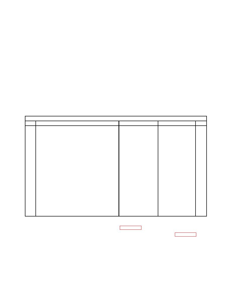
a. Radiator, Bracket, Support, and Hardware
Bill Of Materials
Item
Nomenclature
Part Number
NSN
Qty
3/4" by 3/4" by 1/4"
1
30 inches (76.2 cm)
2
2
3 inches (7.62 cm)
2
2" by 2" by 1/4"
3
18 inch (45.72 cm)
1
4
3 inches (5.08 cm)
2
Hardware
5
Radiator
2 1/2 or 5 ton truck
1
6
Radiator elbow
12253525
1
7
Gasket
10932933
5330-00-058-9263
2
8
Clamp
MS35842-14
4730-00-908-6792
4
9
Hose
11662995
A/R
10
Hose
11662999
A/R
11
Tee, pipe
2090-4-4S
1
12
Clamp
B54-32780
4
13
Drain cock
MS35783-2
1
14
Straight adapter
4738-4-6B
2
15
Plug, elbow flange
2028-16S
1
1. Cut two 1- by 1/4-inch flat bar (1), adjust length to height of radiator. Bend top and bottom of bar to fit
against the top of radiator and floor of stand. See Figure 2-16.
2. Cut 3- by 2-inch by 1/4-inch steel angle 20-1/2 inches long (3) with 45 angle. See Figure 2-16.
3. Cut 2- by 2-inch by 1/4-inch steel angle 10 inches long (4) with 45 angle.
4. Measure studs on radiator of your choice. Use these dimensions to drill two holes in steel angle (3).
5. Weld two steel angles (4) to steel angle (3).
6. Weld radiator bracket/support to powerplant test stand frame on front.

