
TB 43-0209
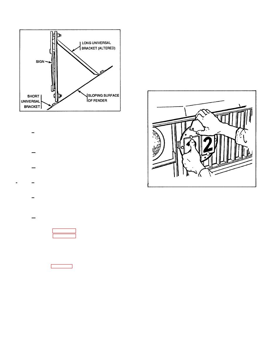
(2) To lock retaining plate, make sure that five
numeral plates are tacked on each anchor pin with the
two top plates showing the desired classification number.
If the vehicle is to be used in combination, position the
retaining plate so that the C on one side of the plate will
be visible. If the vehicle is to be used singly, position the
retaining plate so that the C will not be visible. Press
down firmly on the top of one stack of numeral plates
and slide the retaining plate onto the lock pin until the
plate snaps in place. Repeat the procedure for the
remaining stack of plates and lock the retaining plate to
the remaining lock pin. Refer to FM 5-36 for vehicle
weight classification data.
Figure 26. Sign installed on sloping fender (slope angle
exceeds 30from vertical).
.
3. Install bracket to sign with two bolts (3/4
inch long), P/N 120741, NSN 5306-00-012-0741 two
washers P/N 138538, NSN 5310-00-272-4119, and two
nuts P/N 120368, NSN 5310-00-012-0368.
4. Position the sign in the desired location on
the fender or splash shield. Bend short leg of bracket, as
required, to conform to the contour or slope of fender.
5. Using the short leg of the bracket as a
template, drill two 11/32-inch holes in fender or splash
shield.
Attach the sign to the fender or splash
.
6
shield with two bolts (3/4 inch long), two washers and two
nuts.
7. Secure the altered long universal bracket to
Figure 27. Unlocking the retaining plate.
the sign with one bolt (3/4 inch long), one washer, and
one nut. (Insert bolt in hole located between two stacks
14. OPERATION AND DESIGNATION PLATES.
of numeral plates on sign).
a. These plates, as provided on vehicles and
8. Drill an 11/32-inch hole in fender or splash
equipment, will be kept clear and free from paint at all
shield to correspond with the hole in the altered bracket
times.
and secure the bracket with a bolt (3/4 inch long),
b. Operation plates contain data or instructions on
washer, and nut. Figure 25 shows sign installed on
vehicle operation and will be installed within the normal
splash shield and Figure 26 shows sign installed on
view of the operator when in an operating position. The
sloping fender.
plates will include:
k. Instructions for unlocking and locking the
(1) Road speed plates. To prescribe the
retaining plate are as follows:
maximum permissible speed for operation in each gear
(1) When unlocking retaining plate, use the
ratio and range.
thumb of one hand and press down firmly on one stack
(2) Shift diagram plates. To show the location
of numeral plates, Figure 27. With the other hand, press
of each position of the transmission, transfer, and/or
gently on the retaining plate and pivot the plate away
power takeoff.
from the lock pin. To remove retaining plate completely,
c. Operation plates containing precautionary
press down firmly on the remaining stack of numeral
instructions to avoid personnel injury or equipment
plates and free retaining plate from the other lock pin.
damage will have a red background. This applies to new
plates of photosensitive anodized aluminum, conforming
to type H, MIL-SPEC 15024.
Existing plates will be replaced only when no longer
serviceable.
26

