Custom Search
|
|
 
|
||
|
Fire alarm systems are in two general categories, as determined by the voltage at which the systems operate: line voltage or low voltage. Regardless of the operating voltage, a system may be noncoded or coded. Many older local alarm systems are powered by alternating current (ac) power only with no provision for standby battery power. In these cases, two separate ac circuits (usually 120/240 Vac) are used: one to power the fire alarm system operating circuits and another to power the trouble-signaling circuits of the system. Low-voltage alarm systems, especially those provided with battery standby power, are most often found where some form of automatic fire detection or automatic fire extinguishing is connected to the alarm system. However, recent conversion by most alarm system manufacturers to solid-state electronic design, which is essentially a low-voltage direct-current (dc) technology, means that most recent installations are of the low-voltage type.
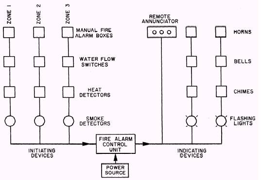
Figure 7-1.\Local fire alarm system diagram. System Power Supply Power supply refers to the circuitry and components used to convert the ac line voltage to low-voltage ac or dc for operating the alarm system and for charging standby batteries. If the system is an older one with a dry cell, nonrechargeable standby battery (no longer permitted by NFPA standards), the power supply probably contains a switching arrangement for connecting the battery to the system when ac power fails. Figure 7-2 is a simplified diagram of a typical dc power supply for powering a low-voltage dc alarm system and for charging a rechargeable standby battery. Transformer T drops the line voltage from 120 volts ac to a voltage in the range of 12 to 48 volts ac. The low ac voltage is rectified by diode bridge D, and the resulting dc voltage powers the alarm system through relay contacts S1 and charges battery B through the current limiting resistor R. When normal ac power is available, energizing relay coil S, contacts S1 are closed. If ac power fails, S1 opens and S2 closes, connecting the battery to the alarm system. Fuse F1 protects against a defect in the power supply or the alarm system during normal ac operation. Fuse F2 protects against alarm circuit defects that would cause a battery overload during dc-powered operation. Removal of resistor R eliminates the battery-charging feature and allows the use of a dry cell battery, which sits idle until ac power fails. At that time, S1 opens and S2 closes, connecting the battery to the alarm system. There are many variations of this basic power supply design. These variations add such features as voltage regulation, current limiting, and automatic high-rate/low-rate charging, controlled by the state of battery charge. All designs normally provide current and voltage meters, pilot lamps, and switches for manual control of charging rate. |
 
|
|
|
||