Custom Search
|
|
 
|
||
|
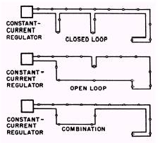
Series Circuits Let's consider a series streetlight system. The power for the circuit will be supplied from the base primary distribution lines, through fuse cutouts, to an oil switch, and from the oil switch to a constant-current regulator. The constantcurrent regulator will supply power to the series loops and, thus, to the individual lamps. While the current (normally 6.6 amperes) remains constant, the voltage will vary with the applied load. A series circuit may be installed with its supply lead and the return lead on the same pole or they may follow a different route. The type of route followed would be known as a closed loop when the leads are on the same pole, and as an open loop when the leads follow a different route. (See fig. 1-4.) If the open-loop method is used, bringing the two conductors to the same pole at several points makes troubleshooting easier (the circuit may be shunted at this point). An open-loop circuit is less expensive initially, but troubleshooting is difficult, time consuming, and costly. Installing the series circuit on the same crossarm as the primary-distribution conductor is usually the most economical. If two primary crossarms are used, the streetlight wires should be carried on the lower arm in the end-pin position. If two separate single-conductor street circuits are on the same crossarm, they should not be placed in adjacent pin positions because of confusion in troubleshooting. Insulator sizes should be based on the open-circuit voltage of the largest regulator used and are usually the same size as those used for primary distribution. White insulators should be used on a series street circuit to distinguish them from the primary distribution insulators and to assist in identifying the circuits for operating and maintenance work. Small strain insulators should be used for cutting in individual lamps or loops of five lamps or fewer. Equivalent voltage insulators with automatic line splices may also be used. If the loop consists of more than five lamps, a primary disk insulator is used. The insulator is usually cut in after the conductors have been strung.
Figure 1-4.\Diagrams of open and closed loops in series circuits. The conductor size should be No. 6 medium hard-drawn copper or its mechanical equivalent. Although No. 8 hard-drawn copper is usually too weak for longer spans, the use of copperweld or similar conductors of high mechanical strength overcomes the difficulty. Conductor sag should be the same as for primary distribution. Constant-current regulators should be protected on overhead circuits by lightning arresters on both the primary and secondary sides.
Multiple Circuits The multiple streetlight system uses a distribution transformer of the proper size as service equipment. (See fig. 1-5.) Notice that the transformer is fed directly through fuse cutouts from the base primary distribution system. The control for the circuit is connected into one line of the secondary side. The selection of output voltage of the transformer depends on the voltage required for the individual lamps that are installed. Depending on the types of lamps selected, this voltage may be from 120 volts to 480 volts. You must know the type of lamp that will be used in the circuit before you can properly select the transformer to feed the streetlight system. While the multiple system is not as dangerous as the series system, it is dangerous, and caution must be exercised by those working on the system.
COMPONENTS AND CONTROLS There are many components required to construct an area lighting system. These include constant-current transformers, relays, controls, fixtures, wiring, and lamps. Controls can be manual, automatic, or a combination.
Figure 1-5.\Multiple light circuit.
|
 
|
|
|
||