Custom Search
|
|
 
|
||
|
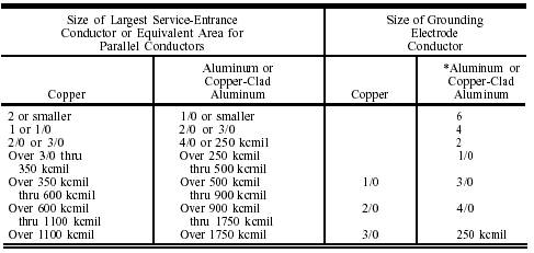
INDUSTRIAL BUILDINGS AND SHOPS Determining electrical service requirements for industrial buildings and shops is quite different from determining dwelling unit services. Branch circuits supplying lighting loads may serve lighting loads only. Receptacle circuits may supply receptacle outlets only. Individual appliances and equipment are identified as special appliance loads or motor loads. The branch circuits supplying these devices are determined by nameplate ratings. TYPES OF INDUSTRIAL LOAD All industrial loads are categorized as continuous or noncontinuous duty, depending on their uses. A load is considered continuous duty if the appliance or motor operates 3 hours or more. Conductors supplying continuous duty loads are required to have an ampacity equal to 125 percent of the total connected load. Conductors for noncontinuous duty loads have to be large enough to supply 100 percent of the total connected load. Industrial loads can be divided into four groups: general lighting loads, general-purpose receptacle loads, special appliance loads, and motor loads. General Lighting Loads Lighting loads for industrial buildings may be computed using the VA-per-square-foot ratio listed in table 3-1. Receptacle loads may not be included in the lighting load calculations. If electric-discharge lighting is used, either the VA-per-square-foot ratio or the sum of all ballasts is used, whichever is larger. Remember, any lighting loads identified as continuous duty is to be computed at 125 percent of the total connected load. The total connected load divided by the circuit breaker rating determines the number of branch circuits required to supply the lighting load. Table 3-6.\Grounding Electrode Conductor for AC Systems
Where multiple sets of service-entrance conductors are used as permitted in Section 230-40, Exception No. 2, the equivalent size of the largest service-entrance conductor shall be determined by the largest sum of the areas of the corresponding conductors of each set. Where there are no service-entrance conductors, the grounding electrode conductor size shall be determined by the equivalent size of the largest service-entrance conductor required for the load to be served. *See installation restrictions in Section 250-92(a). (FPN): See Section 250-23 (b). Exception No. 1: Grounded Systems. a. Where connected to made electrodes as in Section 250-83(c) or (d), that portion of the grounding electrode conductor which is the sole connection to the grounding electrode shall not be required to be larger than No. 6 copper wire or No. 4 aluminum wire. b. Where connected to a concrete-encased electrode as in Section 250-81(c), that portion of the grounding electrode conductor which is the sole connection to the grounding electrode shall not be required to be larger than No. 4 copper wire. c. Where connected to a ground ring as in Section 250-81(d), that portion of the grounding electrode conductor which is the sole connection to the grounding electrode shall not be required to be larger than the conductor used for the ground ring. Exception No. 2: Ungrounded Systems. a. Where connected to made electrodes as in Section 250-83(c) or (d), that portion of the grounding electrode conductor which is the sole connection to the grounding electrode shall not be required to be larger than No. 6 copper wire or No. 4 aluminum wire. b. Where connected to a concrete-encased electrode as in Section 250-81(c), that portion of the grouding electrode conductor which is the sole connection to the grounding electrode shall not be required to be larger than No. 4 copper wire. c. Where connected to a ground ring as in Section 250-81(d), that portion of the grounding electrode conductor which is the sole connection to the grounding electrode shall not be required to be larger than the conductor used for the ground ring. Reprinted with permission from NPFA 70-1990, the National Electrical CodeR, Copyrightc1989, National Fire Protection Association, Quincy, MA 02269. This reprinted material is not the complete and official position of the National Fire Protection Association, on the referenced subject which is represented only by the standard in its entirety. The NECR permits the use of a demand factor for lighting loads installed in the industrial and commercial buildings listed in table 3-2. |
 
|
|
|
||