Custom Search
|
|
  |
|
|
FLOOR PLANS.- Imagine that you want to know the outline of a building, including each partition.
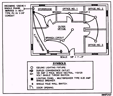
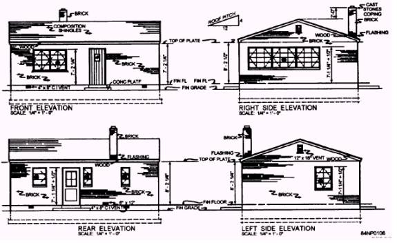
Figure 2-9.- Detail B indicated in figure 2-8. This building is shown in figure 2-10, view A, and you areequippedwithahugesaw. Ifyousawedthe building in half horizontally and looked down on it from above, you would see the complete outline of the building (view B). This particular view directly above would be called a floor plan (view C). Architects and engineers project their thoughts of a building, not yet built, onto a piece of paper and call it a floor plan. It does not matter that the heights of the outlets, appliances, or building parts are different. These heights will be indicated by figures in inches or feet, next to the symbols that represent them. Electrical construction drawings are floor plans modified by the inclusion of electrical symbols. Figure 2-11 shows an electrical layout superimposed on an outline taken from an architectural floor plan The service line that brings power into the house is a three-wire line in 1 1/ 4-inch conduit. The service line feeds power by way of a service switch to a lighting panel, from which three branch circuits run to the lighting fixtures and convenience outlets in the rooms. The symbols for these fixtures and outlets and the service switch are shown at the bottom of figure 2-11. Elevations An elevation is a drawing that represents a view of the finished structure as you would see it from the front, back, left, or right. There are interior elevations, such as a view of a fireplace, as well as exterior elevations, as shown in the elevations of a small building shown in figure 2-12. Doors, windows, shapes of roof, chimneys, and exterior materials are shown. These views provide the viewer with a finished appearance. Few dimensions are given on elevations. Only those vertical dimensions that cannot be shown on the plan are generally included on an elevation view. A Construction Electrician can quickly see from any one of the elevations in figure 2-12 that there is an attic where easy access would be provided to electrical wiring. This is important where there is a requirement for junction boxes that must be accessible. The electrician can also see a foundation wall where, if a service lateral is required, a conduit or sleeve must be placed (for a later run of conduit). This knowledge will allow the electrician to plan ahead to work with the
Figure 2-10.- Floor plan development.
Figure 2-11.- Electrical floor plan layout.
Figure 2-12.- Elevations. Builders when they build the forms. The conduit will be placed in or through the form before the concrete is poured.
|
 
|
|
|