 |
||
|
|
||
| |||||||||||||||
|
|
CONSTRUCTION DRAWINGS Generally, construction or "working" drawings furnish enough information for the Builder to complete an entire project and incorporate all three main groups of drawings-architectural, electrical, and mechanical. In drawings for simple structures, this grouping may be hard to discern because the same single drawing may contain both the electrical and mechanical layouts. In complicated structures, however, a combination of layouts is not possible because of overcrowding. In this case, the floor plan may be traced over and over for drawings for the electrical and mechanical layouts. All or any one of the three types of drawings gives you enough information to complete a project. The specific one to use depends on the nature of construction involved. The construction drawing furnishes enough information for the particular tradesman to complete a project, whether architectural, electrical, or mechanical. Normally, construction drawings include the detail drawings, assembly drawings, bill of materials, and the specifications. A detail drawing shows a particular item on a larger scale than that of the general drawing in which the item appears. Or, it may show an item too small to appear at all on a general drawing. An assembly drawing is either an exterior or sectional view of an object showing the details in the proper relationship to one another. Assembly drawings are usually drawn to a smaller scale from the dimensions of the detail drawings. This provides a check on the accuracy of the design drawings and often discloses errors. Construction drawings consist mostly of rightangle and perpendicular views prepared by draftsmen
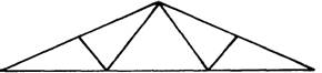
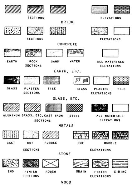
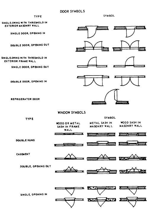
Figure 2-5.-The most commonly used roof trusses. using standard technical drawing techniques, symbols, and other designations as stated in military standards (MIL-STDS). The first section of the construction drawings consists of the site plan, plot plan, foundation plans, floor plans, and framing plans. General drawings consist of plans (views from above) and elevations (side or front views) drawn on a relatively small scale. Both types of drawings use a standard set of architectural symbols. Figure 2-6 illustrates the conventional symbols for the more common types of material used on structures. Figure 2-7 shows the more common symbols used for doors and windows. Study these symbols thoroughly before proceeding further in this chapter.
Figure 2-6.-Architectural symbols for plans and elevations.
Figure 2-7.-Architectural symbols for doors and windows.
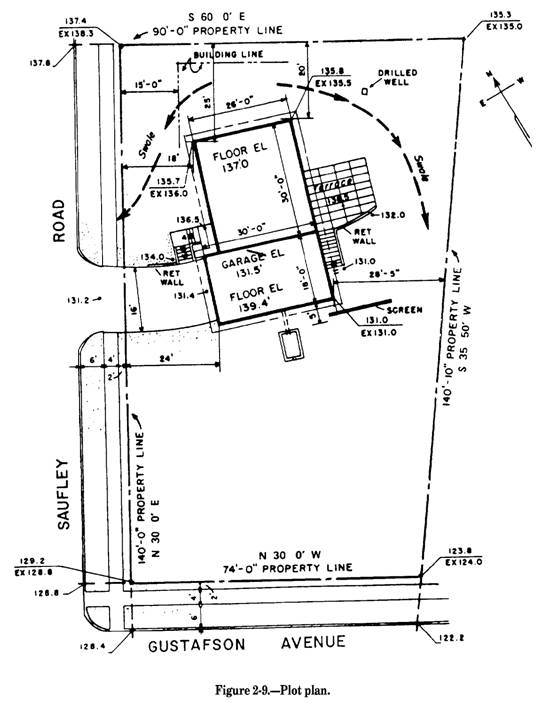
Site Plan A site plan (figure 2-8) shows the contours, boundaries, roads, utilities, trees, structures, and any other significant physical features on or near the construction site. The locations of proposed structures are shown in outline. This plan shows comer locations with reference to reference lines shown on the plot that can be located at the site. By showing both existing and finished contours, the site plan furnishes essential data for the graders. Plot Plan The plot plan shows the survey marks with the elevations and the grading requirements. The plot plan is used by the Engineering Aids to set up the corners and perimeter of the building using batter boards and line stakes, as shown in figure 2-9. Thus, the plot plan furnishes the essential data for laying out the building.
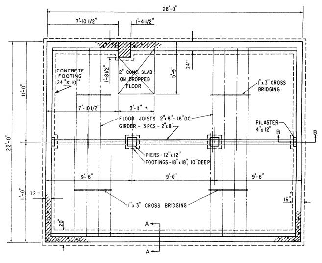
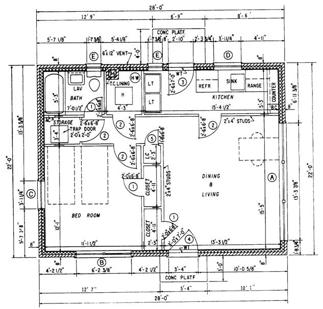
Foundation Plan A foundation plan is a plane view of a structure. That is, it looks as if it were projected onto a horizontal plane and passed through the structure. In the case of the foundation plan, the plane is slightly below the level of the top of the foundation wall. The plan in figure 2-10 shows that the main foundation consists of 12-inch and 8-inch concrete masonry unit (CMU) walls measuring 28 feet lengthwise and 22 feet crosswise. The lower portion of each lengthwise section of wall is to be 12 inches thick to provide a concrete ledge 4 inches wide. A girder running through the center of the building will be supported at the ends by two 4-by- 12-inch concrete pilasters butting against the end foundation walls. Intermediate support for the girder will be provided by two 12-by-12-inch concrete piers, each supported on 18-by- 18-inch spread footings, which are 10 inches deep. The dotted lines around the foundation walls indicate that these walls will also rest on spread footings. Floor Plan Figure 2-11 shows the way a floor plan is developed: from elevation, to cutting plane, to floor plan. An architectural or structural floor plan shows the structural characteristics of the building at the level of the plane of projection. A mechanical floor plan shows the plumbing and heating systems and any other mechanical components other than those that are electrical. An electrical floor plan shows the lighting system and any other electrical systems. Figure 2-12 is a floor plan showing the lengths, thicknesses, and character of the outside walls and
Figure 2-10.-Foundation plan.
Figure 2-11.-Floor plan development.
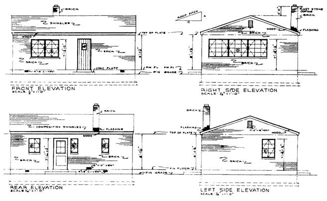
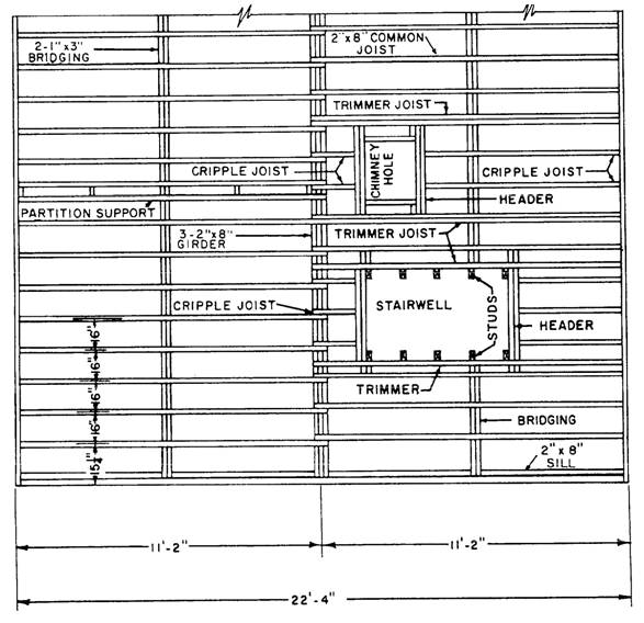
Figure 2-12.-Floor plan. partitions at the particular floor level. It also shows the number, dimensions, and arrangement of the rooms, the widths and locations of doors and windows, and the locations and character of bathroom, kitchen, and other utility features. You should carefully study figure 2-12. In dimensioning floor plans, it is very important to check the overall dimension against the sum of the partial dimensions of each part of the structure. Elevations The front, rear, and sides of a structure, as they would appear projected on vertical planes, are shown in elevations. Studying the elevation drawing gives you a working idea of the appearance and layout of the structure. Elevations for a small building are shown in figure 2-13. Note that the wall surfaces of this house will consist of brick and the roof covering of composition shingles. The top of the rafter plate will be 8 feet 2 1/4 inches above the level of the finished first floor, and the tops of the finished door and window openings 7 feet 13/4 inches above the same level. The roof will be a gable roof with 4 inches of rise for every 12 inches length. Each window shown in the elevations is identified by a capital letter that goes with the window schedule (which we'll discuss later in this chapter). Framing Plans Framing plans show the size, number, and location of the structural members (steel or wood) that make up the building framework. Separate framing plans may be drawn for the floors, walls, and roof. The floor framing plan must specify the sizes and spacing of joists, girders, and columns used to support the floor. When detail drawings are needed, the methods of anchoring joists and girders to the columns and foundation walls or footings must be shown. Wall framing plans show the location and method of framing openings and ceiling heights so that studs and posts can be cut. Roof framing plans show the construction of the rafters used to span the building and support the roof. Size, spacing, roof slope, and all details are shown. FLOOR PLANS.- Framing plans for floors are basically plane views of the girders and joists. Figure 2-14 is an example of a typical floor framing plan.
Figure 2-13.-Elevations.
Figure 2-14.-Floor framing plan. The unbroken, double-line symbol is used to indicate joists, which are drawn in the positions they will occupy in the completed building. Double framing around openings and beneath bathroom fixtures is shown where used. Bridging is shown by a double-line symbol that runs perpendicular to the joists. The number of rows of cross bridging is controlled by the span of the joists; they should not be placed more than 7 or 8 feet apart. A 14-foot span needs only one row of bridging, but a 16-foot span needs two rows. Notes are used to identify floor openings, bridging, and girts or plates. Nominal sizes are used in specifying lumber. Dimensions need not be given between joists. Such information is given along with notes. For example, 1" x 6" joists @ 2'-0" cc indicates that the joists are to be spaced at intervals of 2 feet 0 inches from center to center. Lengths might not be indicated in framing plans. If you find this to be the case, the overall building dimensions and the dimensions for each bay or distances between columns or posts provide such information. ROOF PLANS.- Framing plans for roofs are drawn in the same manner as floor framing plans. A Builder should visualize the plan as looking down on the roof before any of the roofing material (sheathing) has been added. Rafters are shown in the same reamer as joists. |
|
Privacy Statement - Press Release - Copyright Information. - Contact Us - Support Integrated Publishing |