 |
||
|
|
||
| |||||||||||||||
|
|
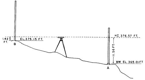
DIFFERENTIAL LEVELING LEARNING OBJECTIVE: Upon completing this section, you should be able to determine elevations in the field to locate points at specified elevations. The most common procedure for determining elevations in the field, or for locating points at specified elevations, is known as differential leveling. This procedure, as its name implies, is nothing more than finding the vertical difference between the known or assumed elevation of a bench mark and the elevation of the point in question. Once the difference is measured, it can (depending on the circumstances) be added to or subtracted from the bench mark elevation to determine the elevation of the new point. ELEVATION AND REFERENCE The elevation of any object is its vertical distance above or below an established height on the earth's surface. This established height is referred to as either a "reference plane" or "simple reference." The most commonly used reference plane for elevations is mean (or average) sea level, which has been assigned an assumed elevation of 000.0 feet. However, the reference plane for a construction project is usually the height of some permanent or semipermanent object in the immediate vicinity, such as the rim of a manhole cover, a rod, or the finish floor of an existing structure. This object may be given its relative sea level elevation (if it is known); or it may be given a convenient, arbitrarily assumed elevation, usually a whole number, such as 100.0 feet. An object of this type, with a given, known, or assumed elevation, which is to be used in determining the elevations of other points, is called a bench mark. PRINCIPLES OF DIFFERENTIAL LEVELING Figure 5-15 illustrates the principle of differential leveling. The instrument shown in the center represents an engineer's level. This optical instrument provides a perfectly level line of sight through a telescope, which can be trained in any direction. Point A in the figure is a bench mark (it could be a concrete monument, a wooden stake, a sidewalk curb, or any other object) having a known elevation of 365.01 feet. Point B is a ground surface point whose elevation is desired. The first step in finding the elevation point of point B is to determine the elevation of the line of sight of the instrument. This is known as the height of instrument and is often written and referred to simply as "H.I." To determine the H.I., you take a backsight on a level rod held vertically on the bench mark (B.M.) by a rodman. A backsight (B.S.) is always taken after a new instrument position is set up by sighting back to a known elevation to get the new H.I. A leveling rod is graduated upward in feet, from 0 at its base, with appropriate subdivisions in feet. In figure 5-15, the backsight reading is 11.56 feet. Thus, the elevation of the line of sight (that is, the H.I.) must be 11.56 feet greater than the bench mark elevation, point A. Therefore, the H.I. is 365.01 feet plus 11.56 feet, or 376.57 feet as indicated. Next, you train the instrument ahead on another rod (or more likely, on the same rod carried ahead) held vertically on B. This is known as taking a foresight. After reading a foresight (F.S.) of 1.42 feet on the rod, it follows that the elevation at point B must be 1.42 feet lower than the H.I. Therefore, the elevation of point B is 376.57 feet minus 1,42 feet, or 375.15 feet. GRADING The term "grade" is used in several different senses in construction. In one sense, it refers to the steepness of a slope; for example, a slope that rises 3 vertical feet for every 100 horizontal feet has a grade of 3 percent. Although the term "grade" is commonly used in this sense, the more accurate term for indicating steepness of slope is "gradient." In another sense, the term "grade" simply means surface. On a wall section, for example, the line that
Figure 5-15.-Procedure for differential leveling. indicates the ground surface level outside the building is marked "Grade" or "Grade Line." The elevation of a surface at a particular point is a grade elevation. A grade elevation may refer to an existing, natural earth surface or to a hub or stake used as a reference point, in which case the elevation is that of existing grade or existing ground. It may also refer to a proposed surface to be created artificially, in which case the elevation is that of prescribed grade, plan grade, or finished grade. Grade elevations of the surface area around a structure are indicated on the plot plan. Because a natural earth surface is usually irregular in contour, existing grade elevations on such a surface are indicated by contour lines on the plot plan; that is, by lines that indicate points of equal elevation on the ground. Contour lines that indicate existing grade are usually made dotted; however, existing contour lines on maps are sometimes represented by solid lines. If the prescribed surface to be created artificially will be other than a horizontal-plane surface, prescribed grade elevations will be indicated on the plot plan by solid contour lines. On a level, horizontal-plane surface, the elevation is the same at all points. Grade elevation of a surface of this kind cannot be indicated by contour lines because each contour line indicates an elevation different from that of each other contour line. Therefore, a prescribed level surface area, to be artificially created, is indicated on the plot plan by outlining the area and inscribing inside the outline the prescribed elevation, such as "First floor elevation 127.50 feet." BUILDING LAYOUT LEARNING OBJECTIVE: Upon completing this section, you should be able to determine boundaries of building layout. Before foundation and footing excavation for a building can begin, the building lines must be laid out to determine the boundaries of the excavations. Points shown on the plot plan, such as building corners, are located at the site from a system of horizontal control points established by the battalion engineering aids. This system consists of a framework of stakes, driven pipes, or other markers located at points of known horizontal location. A point in the structure, such as a building corner, is located on the ground by reference to one or more nearby horizontal control points. We cannot describe here all the methods of locating a point with reference to a horizontal control point of a known horizontal location. We will take, as an illustrative example, the situation shown in figure 5-16. This figure shows two horizontal control points, consisting of monuments A and B. The term "monument," incidentally, doesn't necessarily mean an elaborate stone or concrete structure. In structural horizontal control, it simply means any permanently located object, either artificial (such as a driven length of pipe) or natural (such as a tree) of known horizontal location. In figure 5-16, the straight line from A to B is a control base line from which the building corners of the structure can be located. Corner E, for example, can be located by first measuring 15 feet along the base line from A to locate point C; then measuring off 35 feet on CE, laid off at 90 to (that is, perpendicular to) AB. By extending CE another 20 feet, you can locate building corner F. Corners G and H can be similarly located along a perpendicular run from point D, which is itself located by measuring 55 feet along the base line from A. |
|
Privacy Statement - Press Release - Copyright Information. - Contact Us - Support Integrated Publishing |