 |
||
|
|
||
| |||||||||||||||
|
|
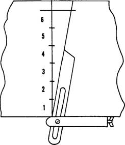
Dovetail Joints The dovetail joint (figure 3-49) is the strongest of all the woodworking joints. It is used principally for joining the sides and ends of drawers in fine grades of furniture and cabinets. In the Seabee units, you will seldom use dovetail joints since they are laborious and time-consuming to make. A through dovetail joint is a joint in which the pins pass all the way through the tail member. Where the pins pass only part way through, the member is known as a blind dovetail joint. The simplest of the dovetail joints is the dovetail half-lap joint, shown in figure 3-60. Figure 3-61 shows how this type of joint is laid out, and figure 362 shows the completed joint.
Figure 3-61.-Laying off 10 angle for dovetail joint.
Figure 3-62.-Making a dovetail half-lap joint. A multiple dovetail joint is shown in figure 3-63; figure 3-64 indicates how the waste is chiseled from the multiple joint. Box Corner Joints With the exception of the obvious difference in the layout, the box corner joint (figure 3-48) is made in a similar manner as the through-multiple-dovetail joint. Coping Joints Inside corner joints between molding trim members are usually made by butting the end of one member against the face of the other. Figure 3-65
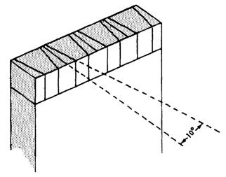
Figure 3-63.-Laying out a pin member for a throughmultiple-dovetail joint.
Figure 3-64.-Chiseling out waste in a through-multipledovetail joint.
Figure 3-65.-Making a coping Joint.
Figure 3-66.-Simple molding and trim shapes.
Figure 3-67.-Typical dimensions for cabinetwork. shows the method of shaping the end of the abutting member to tit the face of the other member. First, saw off the end of the abutting member square, as you would for an ordinary butt joint between ordinary flat-faced members. Then, miter the end to 45, as shown in the first and second views of figure 3-65. Set the coping saw at the top of the line of the miter cut, hold the saw at 90 to the lengthwise axis of the piece, and saw off the segment shown in the third view, following closely the face line left by the 45 miter cut. The end of the abutting member will then match the face of the other member, as shown in the third view. A joint made in this reamer is called a coping joint. You will have to cut coping joints on a large variety of moldings. Figure 3-66 shows the simplest and most common moldings and trims used in woodworking. |
|
Privacy Statement - Press Release - Copyright Information. - Contact Us - Support Integrated Publishing |