 |
||
|
|
||
|
Page Title:
PLANING AND SQUARING TO DIMENSIONS |
||
| |||||||||||||||
|
|
PLANING AND SQUARING TO DIMENSIONS Planing and squaring a small piece of board to dimensions is what you might call the first lesson in woodworking. Like many other things you may have tried to do, it looks easy until you try it. The six major steps in this process are illustrated and described in figure 3-40. You should practice these steps until you can get a smooth, square board with a minimum of planing. JOINTS AND JOINING One basic skill of woodworking is the art of joining pieces of wood to form tight, strong, well-made joints. The two pieces that are to be joined together are called members. The two major steps in
Figure 3-42.-End butt joints with fishplates. making joints are (1) laying out the joint on the ends, edges, or faces and (2) cutting the members to the required shapes for joining. The instruments normally used for laying out joints are the try square, miter square, combination square, the sliding T-bevel, the marking or mortising gauge, a scratch awl, and a sharp pencil or knife for scoring lines. For cutting the more complex joints by hand, the hacksaw dovetail saw and various chisels are essential. The rabbet-and-fillister plane (for rabbet joints) and the router plane (for smoothing the bottoms of dadoes and gains) are also helpful. Simple joints, like the butt (figures 3-41 and 3-42), the lap (figure 3-43), and the miter joints
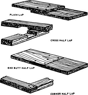
Figure 3-43.-Lap Joints.
Figure 3-44.-Miter joints.
Figure 3-45.-Rabbet joints.
Figure 3-46: Dado and gain joints.
Figure 3-47.-Tenon joints. (figure 3-44), are used mostly in rough or finish carpentry though they may be used occasionally in millwork and furniture making. More complex joints, like the rabbet joints (figure 3-45), the dado and gain joints (figure 3-46), the blind mortise-and-tenon and slip-tenon joints (figure 3-47), the box corner joint (figure 3-48), and the dovetail joints (figure 3-49), are used mostly in making furniture and cabinets and in
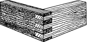
Figure 3-48.-BOX corner joint.
Figure 3-49.-Dovetail joints. millwork. Of the edge joints shown in figure 3-50, the dowel and spline joints are used mainly in furniture and cabinet work, whereas the plain butt and the tongue-and-groove joints are used in practically all types of woodworking. The joints used in rough and finished carpentry are, for the most part, simply nailed together. Nails in a 90 plain butt joint can be driven through the member abutted against and into the end of the abutting member. The joints can also be toenailed at an angle through the faces of the abutting member into the face of the member abutted against, as shown in figure 3-51. Studs and joists are usually toenailed to soleplates and sills. The more complex furniture and cabinet-making joints are usually fastened with glue. Additional strength can be provided by dowels, splines, corrugated fasteners, keys, and other types of joint fasteners. In the dado joint, the gain joint, the mortise-and-tenon joint, the box corner joint, and the dovetail joint, the interlocking character of the joint is an additional factor in fastening. All the joints we have been mentioned can be cut either by hand or by machine. Whatever the method used and whatever the type of joint, remember: To ensure a tight joint, always cut on the waste side of the line; never on the line itself. Preliminary grooving on the waste side of the line with a knife or chisel will help a hacksaw start smoothly. Half-Lap Joints For half-lap joints, the members to be jointed are usually of the same thickness, as shown in figure 3-43.
Figure 3-50.-Edge Joints. The method of laying out and cutting an end butt half lap (figure 3-43) is to measure off the desired amount of lap from each end of each member and square a line all the way around at this point. For a corner half lap (figure 3-43), measure off the width of the member from the end of each member and square a line all the way around. These lines are called shoulder lines. Next, select the best surface for the face and set a marking gauge to one-half the thickness and score a line (called the cheek line) on the edges and end of each member from the shoulder line on one edge to the shoulder line on the other edge. Be sure to gauge the cheek line from the face of each member. This ensures that the faces of each member will be flush after the joints are cut. Next, make the shoulder cuts by cutting along the waste side of the shoulder lines down to the waste side of the cheek line. Then, make the cheek cuts along the waste side of the cheek lines. When all cuts have been made, the members should fit together with faces, ends, and edges flush or near enough to be made flush with the slight paring of a wood chisel. Other half-lap joints are laid out in a similar manner. The main difference is in the method of cutting. A cross half-lap joint may best be cut with a dado head or wood chisel rather than a handsaw. Others may easily be cut on a handsaw, being certain
Figure 3-51.-Toenailing. to cut on the waste side of the lines and making all lines from the face of the material. Miter Joints A miter joint is made by mitering (cutting at an angle) the ends or edges of the members that are to be joined together (figure 3-44). The angle of the miter cut is one-half of the angle formed by the joined members. In rectangular mirror frames, windows, door casing boxes, and the like, adjacent members form a 90 angle, and, consequently, the correct angle for mitering is one-half of 90, or 45. For members forming an equal-sided figure with other than four sides (such as an octagon or a pentagon), the correct mitering angle can be found by dividing the number of sides the figure will have into 180 and subtracting the result from 90. For an octagon (an eight-sided figure), determine the mitering angle by subtracting from 90180 divided by 8 or 90 minus 22.5 equals 67.5. For a pentagon (a five-sided figure), the angle is 90 - (180 / 5) or 90 - 36 = 54 Members can be end mitered to 45 in the wooden miter box and to any angle in the steel miter box by setting the saw to the desired angle, or on the circular saw, by setting the miter gauge to the desired angle. Members can be edge mitered to any angle on the circular saw by tilting the saw to the required angle. Sawed edges are sometimes unsuitable for gluing. However, if the joint is to be glued, the edges can be mitered on a jointer, as shown in figure 3-52. |
|
Privacy Statement - Press Release - Copyright Information. - Contact Us - Support Integrated Publishing |