 |
||
|
|
||
| |||||||||||||||
|
|
PENS Two types of pens are used to produce ink lines: the ruling pen with adjustable blade and the needle-in-tube type of pen (fig. 2-2). We include the ruling pen here only for information; it has been almost totally replaced by the needle-in-tube type. The second type and the one in common use today is a technical fountain pen, or needle-in-tube type of pen. It is suitable for drawing both lines and letters.
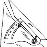
Figure 2-5-Adjustable triangle. The draftsman uses different interchangeable needle points to produce different line widths. Several types of these pens now offer compass attachments that allow them to be clamped to, or inserted on, a standard compass leg. Some of the most common drawing aids are protractors, triangles, and French curves. A protractor (fig. 2-3), is used to measure or lay out angles other than those laid out with common triangles. The common triangles shown in figure 2-4 may be used to measure or lay out the angles they represent, or they may be used in combination to form angles in multiples of 15. However, you may lay out any angle with an adjustable triangle (fig. 2-5), which replaces the protractor and common triangles. The French curve (fig. 2-6) is usually used to draw irregular curves with unlike circular areas where the curvature is not constant. TYPES OF LINES The lines used for engineering drawings must be clear and dense to ensure good reproduction. When making additions or revisions to existing drawings, be sure the line widths and density match the original work. Figure 2-7 shows the common types of straight
Figure 2-6.-French (irregular) curves.
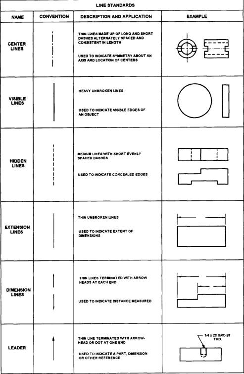
Figure 2-7.-Types of lines.
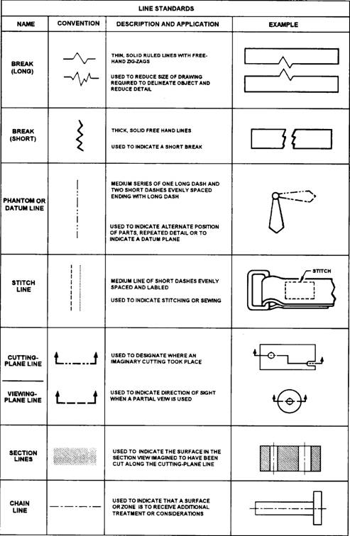
Figure 2-7.-Types of lines-Continued.
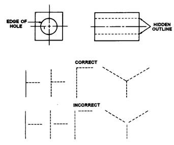
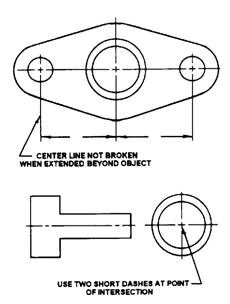
lines we will explain in the following paragraphs. In addition, we will explain the use of circles and curved lines at the end of this section. VISIBLE LINES represent visible edges or contours of objects. Draw visible lines so that the views they outline stand out clearly on the drawing with a definite contrast between these lines and secondary lines. HIDDEN LINES consist of short, evenly-spaced dashes and are used to show the hidden features of an object (fig. 2-8). You may vary the lengths of the dashes slightly in relation to the size of the drawing. Always begin and end hidden lines with a dash, in contrast with the visible lines from which they start, except when a dash would form a continuation of a visible line. Join dashes at comers, and start arcs with dashes at tangent points. Omit hidden lines when they are not required for the clarity of the drawing. Although features located behind transparent materials may be visible, you should treat them as concealed features and show them with hidden lines. CENTER LINES consist of alternating long and short dashes (fig. 2-9). Use them to represent the axis of symmetrical parts and features, bolt circles, and paths of motion. You may vary the long dashes of the center lines in length, depending upon the size of the drawing. Start and end center lines with long dashes and do not let them intersect at the spaces between dashes. Extend them uniformly and distinctly a short distance beyond the object or feature of the drawing unless a longer extension line is required for
Figure 2-8.-Hidden-line technique.
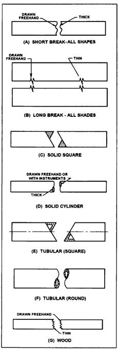
Figure 2-9.-Center-line technique. dimensioning or for some other purpose. Do not terminate them at other lines of the drawing, nor extend them through the space between views. Very short center lines may be unbroken if there is no confusion with other lines. SYMMETRY LINES are center lines used as axes of symmetry for partial views. To identify the line of symmetry, draw two thick, short parallel lines at right angles to the center line. Use symmetry lines to represent partially drawn views and partial sections of symmetrical parts. You may extend symmetrical view visible and hidden lines past the symmetrical line if it will improve clarity. EXTENSION and DIMENSION LINES show the dimensions of a drawing. We will discuss them later in this chapter. LEADER LINES show the part of a drawing to which a note refers. BREAK LINES shorten the view of long uniform sections or when you need only a partial view. You may use these lines on both detail and assembly drawings. Use the straight, thin line with freehand zigzags for long breaks, the thick freehand line for short breaks, and the jagged line for wood parts. You may use the special breaks shown in figure 2-10 for cylindrical and tubular parts and when an end view is not shown; otherwise, use the thick break line. CUTTING PLANE LINES show the location of cutting planes for sectional views.
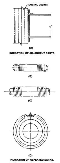
Figure 2-10.-Conventional break lines. SECTION LINES show surface in the section view imagined to be cut along the cutting plane. VIEWING-PLANE LINES locate the viewing position for removed partial views. PHANTOM LINES consist of long dashes separated by pairs of short dashes (fig. 2-11). The long dashes may vary in length, depending on the size of the drawing. Phantom lines show alternate positions of related parts, adjacent positions of related parts, and
Figure 2-11.-Phantom-line application. repeated detail. They also may show features such as bosses and lugs to delineate machining stock and blanking developments, piece parts in jigs and fixtures, and mold lines on drawings or formed metal parts. Phantom lines always start and end with long dashes. STITCH LINES show a sewing and stitching process. Two forms of stitch lines are approved for general use. The first is made of short thin dashes and spaces of equal lengths of approximately 0.016, and the second is made of dots spaced 0.12 inch apart. CHAIN LINES consist of thick, alternating long and short dashes. These lines show that a surface or surface zone is to receive additional treatment or considerations within limits specified on a drawing. An ELLIPSE is a plane curve generated by a point moving so that the sum of the distance from any point on the curve to two fixed points, called foci, is a constant (fig. 2-12). Ellipses represent holes on oblique and inclined surfaces. CIRCLES on drawings most often represent holes or a circular part of an object. An IRREGULAR CURVE is an unlike circular arc where the radius of curvature is not constant. This curve is usually made with a French curve (fig. 2-6). An OGEE, or reverse curve, connects two parallel lines or planes of position (fig. 2-13). |
|
Privacy Statement - Press Release - Copyright Information. - Contact Us - Support Integrated Publishing |