 |
||
|
|
||
|
Page Title:
RADIAL LINE DEVELOPMENT OF CONICAL SURFACES |
||
| |||||||||||||||
|
|
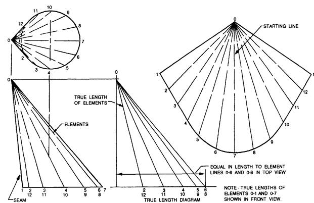
RADIAL LINE DEVELOPMENT OF CONICAL SURFACES The surface of a cone is developable because a thin sheet of flexible material can be wrapped smoothly about it. The two dimensions necessary to make the development of the surface are the slant height of the cone and the circumference of its base. For a right circular cone (symmetrical about the vertical axis), the developed shape is a sector of a circle. The radius for this sector is the slant height of the cone, and the length around the perimeter of the sector is equal to the circumference of the base. The proportion of the height to the base diameter determines the size of the sector, as shown in figure 8-14, view A. The next three subjects deal with the development of a regular cone, a truncated cone, and an oblique cone. Regular Cone In figure 8-14, view B, the top view is divided into an equal number of divisions, in this case 12. The chordal distance between these points is used to step off the length of arc on the development. The radius for the development is seen as the slant height in the front view. If a cone is truncated at an angle to the base, the inside shape on the development no longer has a constant radius; it is an ellipse that must be plotted by establishing points of intersection. The divisions made on the top view are projected down to the base of the cone in the front view. Element lines are drawn from these points to the apex of the cone. These element lines are seen in their true length only when the viewer is looking at right angles to them. Thus the points at which they cross the truncation line must be carried across, parallel to the base, to the outside element line, which is seen in its true length. The development is first made to represent the complete surface of the cone. Element lines are drawn from the step-off points about the circumference to the center point. True-length settings for each element line are taken for the front view and marked off on the corresponding element lines in the development. An irregular curve is used to connect these points of intersection, giving the proper inside shape. Truncated Cone The development of a frustum of a cone is the development of a full cone less the development of the part removed, as shown in figure 8-15. Note that, at all times, the radius setting, either Rl or RZ, is a slant height, a distance taken on the surface of the cones. When the top of a cone is truncated at an angle to the base, the top surface will not be seen as a true circle. This shape must be plotted by established points of intersection. True radius settings for each element line are taken from the front view and marked off on the corresponding element line in the top view. These points are connected with an irregular curve to give the correct oval shape for the top surface. If the development of the sloping top surface is required, an auxiliary view of this surface shows its true shape. Oblique Cone An oblique cone is generally developed by the triangulation method. Look at figure 8-16 as you read this explanation. The base of the cone is divided into an equal number of divisions, and elements 0-1, 0-2, and so on are drawn in the top view, projected down, and drawn in the front view. The true lengths of the elements
Figure 8-15.-Development of a truncated cone.
Figure 8-16.-Development of an oblique cone.
Figure 5-17.-Transition pieces. are not shown in either the top or front view, but would be equal in length to the hypotenuse of a right triangle, having one leg equal in length to the projected element in the top view and the other leg equal to the height of the projected element in the front view. When it is necessary to find the true length of a number of edges, or elements, then a true-length diagram is drawn adjacent to the front view. This prevents the front view from being cluttered with lines. Since the development of the oblique cone will be symmetrical, the starting line will be element 0-7. The development is constructed as follows: With 0 as center and the radius equal to the true length of element 0-6, draw an arc. With 7 as center and the radius equal to distance 6-7 in the top view, draw a second arc intersecting the first at point 6. Draw element 0-6 on the development. With 0 as center and the radius equal to the true length of element 0-5, draw an arc. With 6 as center and the radius equal to distance 5-6 in the top view, draw a second arc intersecting the fast point 5. Draw element 0-5 on the development. This is repeated until all the element lines are located on the development view. This development does not show a seam allowance. |
|
Privacy Statement - Press Release - Copyright Information. - Contact Us - Support Integrated Publishing |