 |
||
|
|
||
| |||||||||||||||
|
|
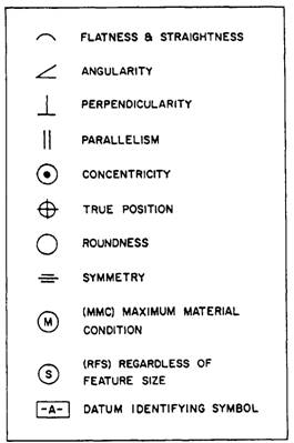
CHAPTER 4 MACHINE DRAWING When you have read and understood this chapter, you should be able to answer the following learning objectives: Describe basic machine drawings. Describe the types of machine threads. Describe gear and helical spring nomenclature. Explain the use of finish marks on drawings. This chapter discusses the common terms, tools, and conventions used in the production of machine drawings. COMMON TERMS AND SYMBOLS In learning to read machine drawings, you must first become familiar with the common terms, symbols, and conventions defined and discussed in the following paragraphs. GENERAL TERMS The following paragraphs cover the common terms most used in all aspects of machine drawings. Tolerances Engineers realize that absolute accuracy is impossible, so they figure how much variation permissible. This allowance is known as tolerance. It is stated on a drawing as (plus or minus) a certain amount, either by a fraction or decimal. Limits are the maximum and/or minimum values prescribed for a specific dimension, while tolerance represents the total amount by which a specific dimension may vary. Tolerances may be shown on drawings by several different methods; figure 4-1 shows three examples. The unilateral method (view A) is used when variation from the design size is permissible in one direction only. In the bilateral method (view B), the dimension figure shows the plus or minus variation that is acceptable. In the limit dimensioning method (view C), the maximum and minimum measurements are both stated The surfaces being toleranced have geometrical characteristics such as roundness, or perpendicularity to another surface. Figure 4-2 shows typical geometrical characteristic symbols. A datum is a surface, line, or
Figure 4-1.-Methods of indicating tolerance.
Figure 4-2.-Geometric characteristic symbols.
point from which a geometric position is to be determined or from which a distance is to be measured. Any letter of the alphabet except 1, O, and Q may be used as a datum identifying symbol. A feature control symbol is made of geometric symbols and tolerances. Figure 4-3 shows how a feature control symbol may include datum references. Fillets and Rounds Fillets are concave metal corner (inside) surfaces. In a cast, a fillet normally increases the strength of a metal corner because a rounded corner cools more evenly than a sharp corner, thereby reducing the possibility of a break. Rounds or radii are edges or outside corners that have been rounded to prevent chipping and to avoid sharp cutting edges. Figure 4-4 shows fillets and rounds. Slots and Slides Slots and slides are used to mate two specially shaped pieces of material and securely hold them together, yet allow them to move or slide. Figure 4-5 shows two types: the tee slot, and the dovetail slot. For examples, a tee slot arrangement is used on a milling machine table, and a dovetail is used on the cross slide assembly of an engine lathe. Keys, Keyseats, and Keyways A key is a small wedge or rectangular piece of metal inserted in a slot or groove between a shaft and a hub to prevent slippage. Figure 4-6 shows three types of keys.
Figure 4-3.-Feature control frame indicating a datum reference.
Figure 4-4.-Fillets and rounds
Figure 4-5.-Slots and slides.
Figure 4-6.-Three types of keys. Figure 4-7 shows a keyseat and keyway. View A shows a keyseat, which is a slot or groove on the outside of a part into which the key fits. View B shows a keyway, which is a slot or groove within a cylinder, tube, or pipe. A key fitted into a keyseat will slide into the keyway and prevent movement of the parts. |
|
Privacy Statement - Press Release - Copyright Information. - Contact Us - Support Integrated Publishing |