Custom Search
|
|
  |
|
|
Vehicles that operate on any public road must be equipped with turn signals. These signals indicate a left or right turn by providing a flashing light signal at the rear and front of the vehicle. The turn-signal switch is located on the steering column (fig. 2-68). It is designed to shut off automatically after the turn is completed by the action of the canceling cam.
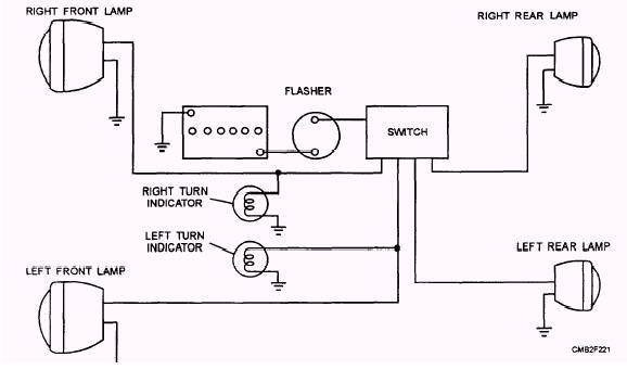
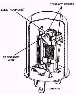
Figure 2-68.- Typical turn-signal switch. A wiring diagram for a typical turn-signal system is shown in figure 2-69. A common design for a turn-signal system is to use the same rear light for both the stop and turn signals. This somewhat complicates the design of the switch in that the stoplight circuit must pass through the turn-signal switch. When the turn-signal switch is turned off, it must pass stoplight current to the rear lights. As a left or right turn signal is selected, the stoplight circuit is open and the turn-signal circuit is closed to the respective rear light. The turn signal flasher unit (fig. 2-70) creates the flashing of the turn signal lights. It consists basically of a bimetallic (two dissimilar metals bonded together) strip wrapped in a wire coil. The bimetallic strip serves as one of the contact points. When the turn signals are actuated, current flows into the flasher- first through the heating coil to the bimetallic strip, then through the contact points, then out of the flasher, where the circuit is completed through the turn-signal light. This sequence of events will repeat a few times a second, causing a steady flashing of the turn signals. BACKUP LIGHT SYSTEM
Figure 2-69.- Typical turn-signal wiring diagram.
Figure 2-70.- Turn signal flasher. pedestrians, whenever the vehicle is shifted into reverse. The backup light system has a fuse, gearshift-or transmission-mounted switch, two backup lights, and wiring to connect these components. The backup light switch closes the light circuit when the transmission is shifted into reverse. The most common backup light switch configurations are as follows: The backup light switch mounted on the transmission and operated by the shift lever. The backup light switch mounted on the steering column and operated by the gearshift linkage. The transmission-or gearshift-mounted backup light switch on many automatic transmission- STOPLIGHT SYSTEM The brake light switch on most automotive equipment is mounted on the brake pedal. When the brake pedal is pressed, it closes the switch and turns on the rear brake lights. On construction and tactical equipment, you may find a pressure light switch. This type of switch uses either air or hydraulic pressure, depending on the equipment. It is mounted on the master cylinder of the hydraulic brake system or is attached to the brake valve on an air brake system. As the brakes are depressed, either air or hydraulic pressure builds on a diaphragm inside the switch. The diaphragm closes allowing electrical current to turn on the rear brake lights. |
 
|
|
|