Custom Search
|
|
  |
|
|
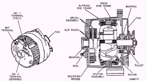
The alternator (fig. 2-21) has replaced the dc generator because of its improved efficiency. It is smaller, lighter, and more dependable than the dc generator. The alternator also produces more output during idle which makes it ideal for late model vehicles. The alternator has a spinning magnetic field. The output windings (stator) are stationary. As the magnetic field rotates, it induces current in the output windings. Alternator Construction
Figure 2-21.- Typical alternator.
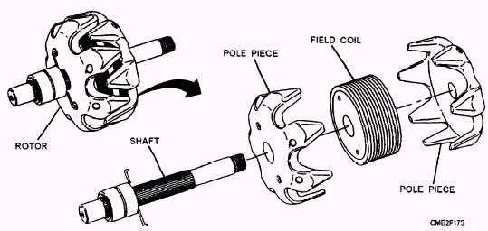
The primary components of an alternator are as follows: ROTOR ASSEMBLY (rotor shaft, slip rings, claw poles, and field windings) STATOR ASSEMBLY (three stator windings or coils, output wires, and stator core) RECTIFIER ASSEMBLY (heat sink, diodes, diode plate, and electrical terminals) ROTOR ASSEMBLY (fig. 2-22).- The rotor consists of field windings (wire wound into a coil placed over an iron core) mounted on the rotor shaft. Two claw-shaped pole pieces surround the field windings to increase the magnetic field. The fingers on one of the claw-shaped pole pieces produce south (S) poles and the other produces north (N) poles. As the rotor rotates inside the alternator, alternating N-S-N-S polarity and ac current is produced (fig. 2-23). An external source of electricity is required to excite the magnetic field of the alternator. Slip rings are mounted on the rotor shaft to provide current to the rotor windings. Each end of the field coil connects to the slip rings. STATOR ASSEMBLY (fig. 2-24).- The stator produces the electrical output of the alternator. The stator, which is part of the alternator frame when assembled, consists of three groups of windings or coils which produce three separate ac currents. This is known as three-phase output. One end of the windings is connected to the stator assembly and the other is connected to a rectifier assembly. The windings are
Figure 2-23.- Simple alternator illustrating reversing magnetic field and resulting current flow.
Figure 2-24.- Stator assembly.
The delta-type stator (fig. 2-26) has the stator wires connected end-to-end. With no neutral junction, two circuit paths are formed between the diodes. A delta-type stator is used in high output alternators. |
 
|
|
|