Custom Search
|
|
  |
|
|
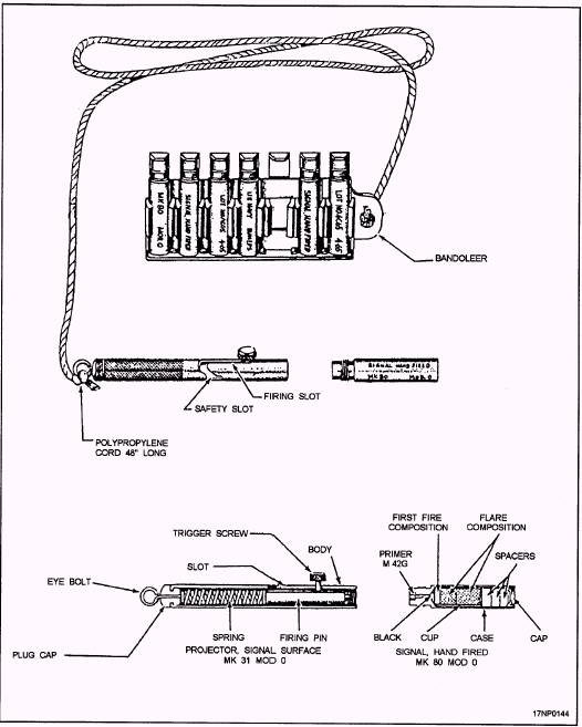
MK 79 MOD 0 ILLUMINATION SIGNAL KIT The Mk 79 Mod 0 signal kit (fig. 4-5) consists of a Mk 31 Mod 0 signal projector, a plastic bandoleer that holds seven Mk 80 Mod 0 signals, and an instruction sheet. The kit is used by downed aircrew personnel as a distress signaling device. Because it is small and lightweight, personnel can carry it in pockets of flight suits or in life rafts. The projector aims and fires the signals. Each signal contains a single red star. On activation, this star is propelled upward to a height of between 250 and 650 feet. The star burns for a minimum of 4 1/2 seconds. To operate the device, you cock the projector firing pin by moving the trigger screw to the bottom of the vertical slot, and slip it to the right so that it catches at the top of the angular slot. After cocking the firing pin, remove a signal from the bandoleer and mate the projector with the signal. Now, rotate the projector clockwise until the signal is seated. Hold the projector overhead, pointed at a slight angle away from your body. While firmly gripping the projector, fire the signal by slipping the trigger screw to the left, out of the safety slot and into the firing slot. NOTE: This first step is very important because the signal is threaded and screwed into the end of the projector. If you don't cock the projector before screwing in the signal, the firing pin could be forced into the primer of the signal, possibly firing the signal prematurely.
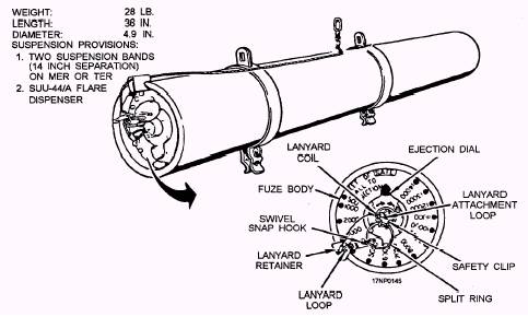
Figure 4-5.-Mk 79 Mod 0 illumination signal kit. 4-4 AREA AND TARGET ILLUMINATING DEVICES LEARNING OBJECTIVE: Identify the purpose and use of area and target illuminating devices to include components and operation. The illuminating devices discussed in this chapter are designed to be launched or dropped from aircraft. Aircraft flares are used to illuminate large areas for bombardment, reconnaissance, emergency aircraft landing, or any other purpose where a high-intensity light is required. MK 45 MOD 0 AIRCRAFT PARACHUTE FLARE The aircraft-launched Mk 45 Mod 0 aircraft parachute flare (fig. 4-6) is used for night illumination of surface areas in search-and-attack operations. It replaces the Mk 24 Mods aircraft parachute flare. The Mk 45 Mod 0 aircraft parachute flare is as an AUR, complete with the candle, parachute assembly, and fuze. All components are encased in a cylindrical aluminum body approximately 36 inches long (including the fuze assembly) and 4.9 inches in diameter. The Mk 364 Mod 0 fuze is shipped installed in the flare. Its sole purpose is to control the altitude of flare ejection in relation to launch altitude. It does not directly control candle ignition. The fuze has 15 functional settings and 1 SAFE setting. The functional settings are at 1,000-foot intervals from 1,000 to 14,000 feet, except that 1 minimum setting of 500 feet is provided. The fuze-setting mechanism consists of a single yellow dial indicator you can easily turn by hand-clockwise for setting and counterclockwise for safing. A spring-loaded detent holds the dial indicator at a selected setting or at SAFE, and prevents accidental changing of the setting by vibration forces. The Mk 45 Mod 0 flare is launched from an available external launching system, such as bomb racks. The launching system provides a 14-inch suspension, or the flare is launched from an aircraft by hand. It is usually dispenser launched. A drogue tray
Figure 4-6.-Mk 45 Mod 0 aircraft parachute flare. 4-5
Figure 4-7.-Mk 45 Mod 0 aircraft parachute flare with drogue tray. (fig. 4-7) is used to dispenser launch the flare. Normally, the drogue tray is configured to the flare at the time of manufacture. The drogue tray is a quarter-round, lightweight, aluminum channel with perpendicular ends. The fuze end has an attachment tab and a circular opening to allow for flare fuze setting. It is attached to the safety clip by a lanyard. The opposite end is solid and has a red plastic seal that acts as a pressure seal for dispenser ejection cartridge gases. Flares and trays are loaded into the dispenser as a unit. Regardless of launch method, the flare is initiated by exerting pull on the lanyard. When the lanyard is pulled, it snaps the safety clip from its position over the toggle. A force of 18 to 35 pounds pulls the internal disconnect completely out of the fuze mechanism, allowing the spring-loaded striker to strike the primer. The primer ignites a fixed, 2-second delay element and drives the plunger into the ejection time-delay fuze at a point determined by the selected setting. After 2 seconds, the delay element ignites black powder in the plunger. Ignition is transferred through a perforation in the plunger to the time-delay fuze. After the preset delay, the fuze ignites the expellant. The expellant forces off the aluminum end cap and expels the candle and the parachute assembly from the flare case with considerable force. Upon opening, the main parachute pulls on the cables of the suspension/ignition system. The shorter cable pulls the release pin from the igniter assembly, cocking and releasing the firing pin so that it strikes the primer. The primer ignites an ignition pellet, which, in turn ignites the magnesium candle. The burning candle is then suspended on the fully deployed main parachute. When the candle approaches the end of its burning time, its heat activates the explosive bolt. (Ten of the eighteen shroud lines are attached to the explosive bolt.) Release of these shroud lines causes the parachute to collapse and flutter to the ground. |
 
|
|
|