Custom Search
|
|
  |
|
|
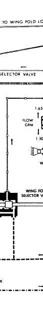
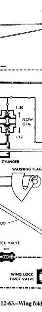
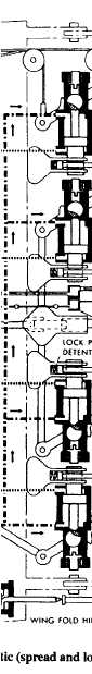
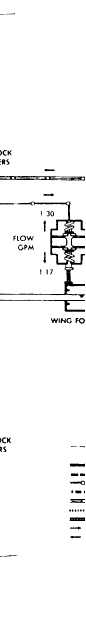
WING FOLD SYSTEMS There are miscellaneous differences in the design and operating characteristics of the various hydraulically operated systems, and the wing fold systems are no exception. Basically similar components perform similar functions with only minor variation in part nomenclature and physical design. The wing fold system described in the following paragraphs will point out some of these differences. Refer to the wing fold system schematic shown in figure 12-63 as you read the following paragraphs. The wings arc unlocked by lifting the wing fold handle up and forward until it reaches the first stop. This action operates the cable and pushrod mechanisms that control mechanical locking of the wing lock cylinders. This same action, through the pushrod connected to the mechanical locks, causes the warning flags to appear on top of the wings. Further movement of the wing fold handle at this point is prevented by a spring-loaded mechanical latch that blocks the crank at the wing lock cylinder. With flight controls in the proper position and weight on the wheels, the wing fold lockpin switch is placed at UNLOCK. Power is supplied to the unlock side of the wing lock selector valve, allowing combined system utility hydraulic pressure to the four wing lock cylinders in each wing. Pressure in the wing lock cylinders moves the lock shaft to retract the wing lockpins. After completion of this action, the wing fold control handle can be moved to the full forward position, operating the wing fold selector valve in each wing and porting hydraulic pressure through flow regulators to the wing fold actuating cylinders, which extend and cause the wing to fold. The wings are spread by moving the wing fold control handle aft to the first stop, mechanically positioning the wing fold selector valve in each wing to port hydraulic pressure through flow regulators to the wing fold cylinders, causing them to retract and spread the wings. The wing fold control handle is held at the first stop by the retracted lockpins, which prevent rotation of the lock shafts and cranks.
After spreading action, the wing fold lockpin switch is placed at LOCK and power is supplied to the lock side of the wing lock selector valve. The selector valve then ports hydraulic pressure to the closed timer valve in each wing fold joint. As spreading is completed, a spring-loaded lockpin detent in each inboard wing lock fitting is depressed by the outboard lock fitting. When the lock fittings are aligned, the lockpins can extend and enter the wing lock fittings. With lockpins extended, the lock shaft is free to rotate, and the wing fold control handle can be moved flush with the top surface of the center console. This action rotates the lock shafts to prevent retraction of the lockpins and retracts the warning flags. When any lockpin fails to extend, the wing fold handle cannot be secured, and the warning flags will remain exposed. A thermal relief valve is installed in the pressure line of the wing fold and wing lock selector valves. It vents excessive pressure buildup because of the thermal expansion of trapped fluid into the combined system return lines. When pressure increases above 3,730 to 3,830 psi, the spring-loaded ball check unseats, and the valve relieves excessive pressure. The spring-loaded ball check reseats when pressure falls to 3,360 psi. Maintenance of the wing fold system at the organizational level consists mainly of scheduled inspections, lubrication, rigging of mechanical linkages, removal and installation of components, and analysis of system malfunctions. The MIM provides system schematics and trouble analysis sheets to assist in pinpointing causes of mal-functions. A thorough knowledge of the system before troubleshooting is necessary. Logical reasoning plus a systematic operational checkout of the system will produce better results than trial and error trouble-shooting methods. Lack of lubrication or other required maintenance at prescribed intervals will generally be reflected by stiff, hard-to-operate wing fold control mechanisms or related wing fold discrepancies. Strict compliance with maintenance requirements, in all cases, will eliminate or minimize this possibility. All corrective maintenance should be in accordance with the instructions provided in the appropriate MIM. Wing lock warning flags rarely get out of adjust-ment, and whenever they fail to retract, it should be considered an indication of failure of all locks to properly enter lock fittings. Realignment to provide a wing lock indication without ensuring that the wings are positively locked certainly does not correct the discrepancy and presents an extremely hazardous flight condition. Good maintenance practices, strict quality assur-ance by qualified inspectors, and good supervision will ensure safe, timely, and quality corrective maintenance actions. Intermediate maintenance of wing fold hydraulic components generally consists of installing cure-date repair kits (sealing devices, etc.) and/or replacement of miscellaneous parts available as fleet-type repair kits. Parts in the repair kit are normally easy-to-replace items, which do not require the depth of disassembly and inspection necessary at complete overhaul, and are replaced whenever high time removal of a component is necessary. Information on repair kits for various components is provided in the applicable "Illustrated Parts Breakdown" and, in some cases, the "Intermediate Maintenance" section of the MIM and appropriate (03) overhaul manuals. Step-by-step procedures for the repair of com-ponents are provided in the "Intermediate Maintenance" section of some MIMs and/or 03 manuals. In general, repairs will consist of cleaning, disassembly, inspection, replacement of failed parts, reassembly, and testing. Inspection of disassembled components includes checking for visible damage to internal parts, thread damage, condition of plating, wear limitations, spring distortion, specified free length of spring, and corrosion. In some cases, nondestructive inspection of critical parts to detect discontinuities and fatigue cracks is required. Reassembly will normally be in the reverse order of disassembly and will include proper installation of parts, seals, packings, retainers, torquing, safety wiring, and cotter keying, as applicable. Test of the component following repair will further verify its ability to perform its intended function and will generally consist of proof testing, static leak testing, and operational testing. Throughout the complete intermediate level repair operation, the components undergoing repair must be subjected to quality assurance verification of specified repair steps as indicated in the applicable MIM or (03) overhaul manual. It is NOT sufficient to eliminate the progressive quality assurance and verify the operation of the end product. Stationary test benches used for testing hydraulic components are filled with preservative hydraulic fluid. Repaired components that are not to be installed immediately must be tilled with MIL-H-46170 unless otherwise specified. All openings are capped or plugged
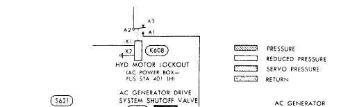
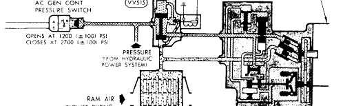
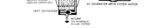
Figure 12-64.AC generator drive system. with approved metal closures. Repaired components that are to be installed immediately subsequent to bench testing should be drip-drained, capped, and plugged as neccessary. Plastic plugs are prohibited because of the possibility of plastic chips entering the component and damaging seals or blocking critical passages. The man-hours expended in correcting mal-functions are documented on a VIDS/MAF. When apart is removed and is to be processed through the IMA for repairs, an additional VIDS/MAF is initiated with the appropriate information tilled in and attached to the component for turn-in. Consult the appropriate manuals for proper documentation of the VIDS/MAF. The job is not considered complete until the necessary paperwork has been completed screened, and turned in. |
 
|
|
|