Custom Search
|
|
  |
|
|
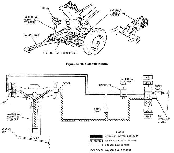
CATAPULT LAUNCH SYSTEM The purpose of the nose landing gear catapult launch system is to provide a means of directing the aircraft into position for catapult launching, as well as being connected automatically to the ships catapult equipment. Such a device eliminates the necessity for flight deck personnel to manually connect catapult
Figure 12-61.Catapult system hydraulic schematic. harnesses. The system consists of a catapult launch bar, a launch bar actuating cylinder and gimbal, selector valve, leaf retracting springs, and a catapult tension bar socket. See figure 12-60. The launch bar is swivel mounted on the forward side of the nose gear outer cylinder and maybe extended and retracted during taxiing. The launch bar is automatically retracted after catapulting. A launch bar warning light on the main instrument panel comes on any time the following conditions exist: The launch bar control switch is in EXTEND. The selector valve is in bar extended position. The launch bar is not up and locked with weight off the landing gear. The launch bar control switch is in RETRACT and the launch bar actuator is not up and locked. Accessories for the catapulting system include a tension bar and a catapult holdback bar. The catapult tension bar socket is mounted on the nose gear axle beam and provides for attachment of the tension bar for tensioning of the airplane prior to catapulting. The catapult system, shown in figure 12-61, is selected to extend by placing the launch bar control switch in the cockpit to the EXTEND position. With weight on the gear, this action completes an electrical
Figure 12-62.Air refueling probe hydraulic system. circuit to energize solenoid A of the launch bar selector valve. The energized selector valve directs hydraulic system pressure to the launch bar actuating cylinder extend port. Hydraulic pressure unlocks locking fingers in the launch bar actuating cylinder and extends the actuator rod end. The actuator rod end is attached to the launch bar, and as the actuator extends, it lowers the launch bar. As the launch bar moves down, it encloses two horns on the nose gear axle beam, enabling the launch bar to steer the nose gear. Before the airplane reaches the catapult, the tension and holdback bars are attached to the tension bar socket. As the airplane approaches the catapult, the launch bar enters a track that permits the bar to steer the nose gear for alignment with the catapult. The top of the launch bar actuating cylinder is gimbal-mounted to permit rotation in all directions as the launch bar turns and is raised and lowered. As the airplane moves forward, aligned with the catapult, the launch bar automatically engages the catapult shuttle. The shuttle is advanced to tension the airplane on the catapult. The launch bar switch is placed in OFF, de-energizing the selector valve. When catapult pressure reaches a predetermined value the tension bar breaks and the airplane is catapulted off the deck. In the de-energized position, the selector valve connects the launch bar actuator extend and retract ports to the hydraulic return circuit. The launch bar is held in the down position by the catapult shuttle until reaching the end of the launch run, where the bar is released from the shuttle and the weight-on-gear switch is actuated to the weight-off-gear position. When the switch is activated to the weight-off-gear position, a power circuit is completed to energize the retract solenoid of the launch bar selector valve. The energized valve directs hydraulic pressure to retract the launch bar actuating cylinder, automatically retracting and locking the launch bar. Two leaf springs on each side of the launch bar shank raise the launch bar to the retracted position if automatic hydraulic retraction fails. When the piston is fully retracted locking fingers on the piston lock the actuator and launch bar in the retracted position. Hydraulic retraction of the launch bar is obtained by holding the launch bar control switch in RETRACT. This action completes an electrical circuit to energize the launch bar selector valve retract solenoid (solenoid B). The energized selector valve directs hydraulic pressure to retract the launch bar actuator. The actuator retracts, pulling the launch bar up and locking the actuator and launch bar in the retracted position. |
 
|
|
|